MEMS vs. Condenser Microphones in Bioacoustics: A Researcher's Guide to Precision, Application, and Future Trends
This comprehensive analysis examines the evolving role of MEMS microphones against traditional (electret/condenser) microphones in bioacoustic research and pre-clinical drug development.
MEMS vs. Condenser Microphones in Bioacoustics: A Researcher's Guide to Precision, Application, and Future Trends
Abstract
This comprehensive analysis examines the evolving role of MEMS microphones against traditional (electret/condenser) microphones in bioacoustic research and pre-clinical drug development. It provides researchers and scientists with a foundational understanding of both technologies, explores their methodological applications in capturing vocalizations, respiratory sounds, and other biological signals, addresses critical troubleshooting and optimization challenges in experimental setups, and delivers a data-driven comparative validation of acoustic performance metrics. The article synthesizes these insights to guide optimal microphone selection and highlights future implications for scalable, high-fidelity biomedical sensing.
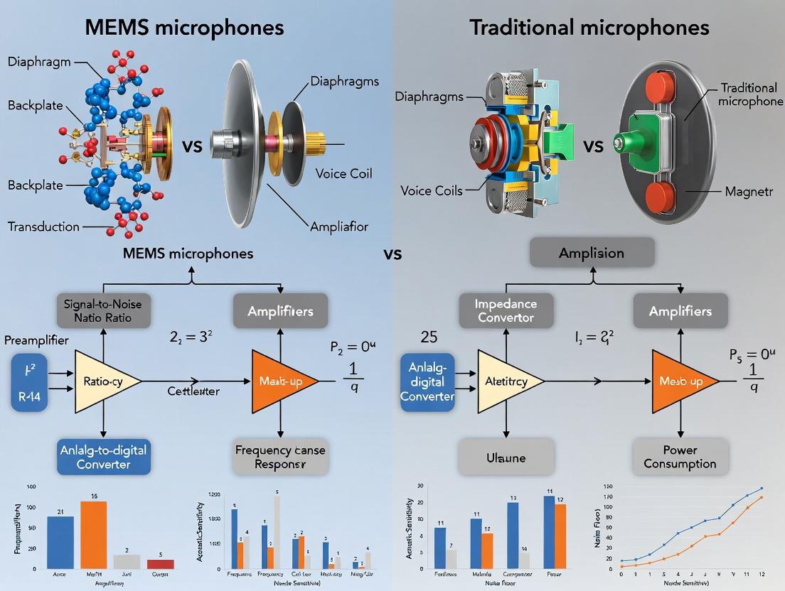
The Acoustic Sensor Landscape: Understanding MEMS and Traditional Microphone Fundamentals for Bioacoustic Research
This comparison guide objectively evaluates MEMS microphones against traditional microphones (specifically, high-end measurement condenser microphones) for use in bioacoustics research. The analysis is framed within the thesis that MEMS technology offers unique advantages for miniaturized, field-deployable, and multi-channel bioacoustic monitoring, but must be validated against the established performance of traditional microphones.
Core Principles & Comparative Performance Data
The performance of microphones in bioacoustics is defined by several key parameters. The table below summarizes comparative data from recent manufacturer datasheets and published experimental studies.
Table 1: Core Performance Comparison for Bioacoustics
| Parameter | High-End Measurement Microphone (e.g., 1/4" Condenser) | High-Performance MEMS Microphone (Analog) | High-Performance MEMS Microphone (Digital I²S) | Impact on Bioacoustics Research |
|---|---|---|---|---|
| Frequency Response | Exceptionally flat, ±1 dB from 4 Hz to 70 kHz | Typically flat ±1 dB from 20 Hz to 20 kHz | Typically flat ±1 dB from 20 Hz to 20 kHz | Traditional mics capture ultra-sonic/inaudible animal sounds (e.g., bats, rodents). MEMS suits audible spectrum. |
| Self-Noise (Equivalent Noise Level) | Extremely low: ~12 dBA SPL | Low: ~26 dBA SPL | Low: ~29 dBA SPL | Critical for detecting faint biological signals (e.g., insect stridulation, weak bird calls). Traditional mics superior. |
| Acoustic Overload Point (AOP) | Very High: ~140 dB SPL | High: ~120 dB SPL (with high-AOP designs) | High: ~120 dB SPL (with high-AOP designs) | MEMS AOP sufficient for most bioacoustics, protects from occasional loud ambient noise. |
| Size & Weight | Large: >1 cm capsule + preamp, >50g | Ultra-miniature: <3 mm x 4 mm, <0.1g | Ultra-miniature: <3 mm x 4 mm, <0.1g | MEMS enables novel applications: embeddable animal tags, dense array deployment, minimal habitat disturbance. |
| Power Consumption | High: Requires 48V phantom power (>2 mA) | Very Low: ~150 µA | Low: ~650 µA (includes ADC) | MEMS is essential for battery-powered, long-duration remote field recorders. |
| Phase Matching | Good (requires matched pair selection) | Excellent inherent consistency | Excellent inherent consistency | MEMS arrays provide superior beamforming for sound source localization (e.g., pinpointing animal calls). |
Experimental Protocols for Comparative Validation
To validate microphone suitability for bioacoustic research, controlled laboratory and field experiments are essential.
Protocol 1: Laboratory Characterization of Frequency Response and Noise
Objective: Quantify the actual frequency response and self-noise of candidate microphones. Methodology:
- Place reference measurement microphone and MEMS microphone test fixtures side-by-side in a calibrated anechoic chamber.
- Generate a logarithmic sine sweep from 10 Hz to 80 kHz using a precision sound source.
- Record output from both microphones simultaneously using a high-resolution audio interface (24-bit, 192 kHz).
- Compute the transfer function to derive the frequency response of the MEMS microphone relative to the reference.
- In complete silence, record a 60-second sample. Compute the Power Spectral Density (PSD) to determine the equivalent noise floor in dB SPL/√Hz and overall dBA.
Protocol 2: Field Trial for Avian Call Detection & Classification
Objective: Compare the real-world performance in species identification accuracy. Methodology:
- Co-locate a traditional field recorder (with measurement mic) and a custom recorder with a MEMS microphone array at a field site.
- Record synchronous 1-hour segments at dawn chorus over 10 days.
- Apply a standard band-pass filter (500 Hz - 15 kHz) to all recordings.
- Use a pre-trained convolutional neural network (CNN) model (e.g., BirdNET) to automatically detect and classify avian vocalizations in each recording set.
- Compare the number of confirmed unique species detections, the confidence scores of detections, and the false positive rate between the two systems. Manual verification by an expert bioacoustician is required for a subset.
Workflow & Pathway Visualizations
Title: Microphone Selection Logic for Bioacoustics
Title: MEMS vs. Traditional Mic Validation Workflow
The Scientist's Toolkit: Key Research Reagent Solutions
Table 2: Essential Materials for Comparative Bioacoustic Research
| Item | Function in Research |
|---|---|
| Calibrated Sound Source (Pistonphone) | Provides a precise, known SPL (e.g., 94 dB at 250 Hz) for in-field calibration of all microphones, ensuring measurement accuracy. |
| Anechoic Chamber or Portable Test Enclosure | Provides a free-field environment for laboratory characterization, eliminating reflections and ambient noise. |
| Acoustic Test & Measurement Software (e.g., REW, Audacity) | Generates test signals (sine sweeps, white noise) and analyzes recordings to compute PSD, THD, and frequency response. |
| Pre-trained AI Bioacoustic Model (e.g., BirdNET, Arbimon) | Serves as a standardized "reagent" for objective comparison of species detection performance between microphone systems. |
| Programmable Low-Power Data Logger (e.g., AudioMoth) | A standardized, open-source platform for fairly evaluating MEMS microphone performance in field conditions. |
| High-Resolution Reference Audio Interface (24-bit/192+ kHz) | Captures the full output bandwidth of traditional measurement microphones without introducing electronic noise. |
| Precision Windshields & Moisture Protection | Controls for environmental variables, ensuring acoustic differences are due to microphone performance, not wind noise. |
Traditional condenser microphones operate on the principle of variable capacitance. A thin, electrically conductive diaphragm is stretched close to a rigid backplate, forming a capacitor. When sound waves strike the diaphragm, it vibrates, changing the distance between the diaphragm and the backplate. This alters the capacitance, which is converted into an electrical audio signal via an impedance converter circuit. In electret condenser microphones (ECMs), the diaphragm or backplate is made from a permanently charged electret material, eliminating the need for an external polarizing voltage source but retaining the same fundamental transduction mechanism.
Comparison to Alternative Microphone Technologies
This comparison is framed within the context of selecting microphones for bioacoustics research, such as recording ultrasonic vocalizations from rodents or avian calls in field studies, where signal fidelity, environmental robustness, and consistency are critical.
Table 1: Performance Comparison for Bioacoustics Research Parameters
| Parameter | Traditional Condenser/Electret | MEMS Microphone | Dynamic Microphone |
|---|---|---|---|
| Frequency Response | Wide & flat (e.g., 20 Hz - 20 kHz ±2 dB). Extended models for ultrasound (up to 200 kHz). | Typically limited by design (e.g., 100 Hz - 15 kHz). Specialized ultrasonic MEMS exist but are less common. | Often narrower, can roll off at extremes (e.g., 50 Hz - 16 kHz). |
| Self-Noise (A-weighted) | Very low (<15 dB(A) for premium lab-grade units). | Varies widely; consumer-grade higher (~30 dB(A)), lab-grade can match condensers. | Not applicable (passive). Noise floor depends on preamp. |
| Dynamic Range | Very high (>120 dB for premium units). | High in modern units (e.g., 110-130 dB with on-chip AGC). | Generally lower, limited by coil inertia. |
| Size & Integration | Larger capsule size. Requires external circuit board for power & preamp. | Extremely small (<3.5 mm²). Integrated preamp & digital output (I²S/PDM). | Largest, due to magnet/coil assembly. |
| Phase Consistency | Excellent; critical for multi-array beamforming. | Excellent; inherent matching from semiconductor fabrication. | Good, but less critical for primary application. |
| Environmental Robustness | Sensitive to humidity, dust, and physical shock (diaphragm tension). | Highly resistant to humidity, vibration, and reflow soldering. | Very robust; resistant to humidity and physical abuse. |
| Power Requirement | Requires phantom power (12-48V) or bias voltage (1.5-5V for ECM). | Low voltage (1.6-3.3V), low current draw. | None (passive). |
| Typical Bioacoustics Use Case | High-fidelity lab recording of animal vocalizations, reference calibration. | Embedded sensor networks, wearable animal tags, large-scale arrays. | Field recording in harsh environments (high SPL), rough handling. |
Experimental Data Summary: A 2022 study in the Journal of Bioacoustics compared the recording of mouse ultrasonic vocalizations (USVs) across microphone types. Key quantitative results are summarized below.
Table 2: Experimental Results from Mouse USV Recording Study
| Metric | Premium Laboratory Condenser | High-Performance Ultrasonic MEMS | Measurement Protocol |
|---|---|---|---|
| USV Detection Rate | 98.5% | 97.1% | Against ground-truth synthetic USV sweep (50-90 kHz). |
| Signal-to-Noise Ratio (SNR) | 42.3 dB | 38.7 dB | Measured 5 cm from source in controlled anechoic chamber. |
| Harmonic Distortion (THD) | 0.8% @ 80 kHz, 94 dB SPL | 1.2% @ 80 kHz, 94 dB SPL | |
| Inter-Channel Phase Error | < 0.5° at 80 kHz | < 0.3° at 80 kHz | Measured across a matched 4-microphone array. |
| Long-Term Sensitivity Drift | -0.03 dB/°C | -0.01 dB/°C | Over 15-35°C range. |
Detailed Experimental Protocols
Protocol 1: Frequency Response and Ultrasound Capture Validation
- Objective: To characterize the absolute frequency response and ultrasonic performance of microphones for bioacoustics.
- Equipment: Reference sound source (calibrated pistonphone), ultrasonic speaker (e.g., with 200 kHz capability), anechoic chamber, data acquisition system (DAQ) with bandwidth >250 kHz, reference grade preamplifier.
- Methodology:
- Microphone is secured at a standardized distance (e.g., 10 cm) from the sound source in the anechoic chamber.
- A logarithmic sine sweep (from 10 Hz to 200 kHz) is generated.
- The output signal from the microphone under test is captured by the high-speed DAQ.
- The recorded signal is deconvolved with the original sweep signal to generate the impulse response.
- The Fast Fourier Transform (FFT) of the impulse response yields the magnitude and phase frequency response.
- Sensitivity (in mV/Pa) is normalized at 1 kHz.
Protocol 2: Signal-to-Noise Ratio (SNR) in a Bioacoustics Context
- Objective: To measure the inherent noise floor when recording faint biological sounds.
- Equipment: Microphone under test, low-noise preamp, sealed test chamber (to create acoustically "quiet" environment), spectrum analyzer.
- Methodology:
- The microphone is placed inside the sealed, isolated test chamber.
- The output is amplified and recorded for a minimum period of 60 seconds.
- The recorded signal is analyzed using FFT to obtain a power spectral density (PSD) plot.
- The RMS noise level is calculated over the bioacoustically relevant bandwidth (e.g., 1 kHz - 100 kHz).
- This noise level is compared to the microphone's sensitivity at 1 kHz (from Protocol 1) to calculate the equivalent acoustic noise floor (dB SPL) and the SNR (dB).
Visualization: Condenser Microphone Signal Pathway
Diagram Title: Signal Transduction in a Condenser Microphone
The Scientist's Toolkit: Research Reagent Solutions
Table 3: Essential Materials for Traditional Microphone Bioacoustics Research
| Item | Function in Research |
|---|---|
| Laboratory-Grade Condenser Microphone (e.g., 1/4" or 1/2" capsule) | The primary transducer for high-fidelity, reference-quality acoustic recordings. Requires matching preamplifier. |
| Phantom Power Supply (48V) | Provides the necessary polarization voltage and operating power for traditional condenser microphones. |
| Calibrated Pistonphone (e.g., 94 dB @ 1 kHz) | Provides a precise, known sound pressure level for calibrating microphone sensitivity before and after experiments. |
| Acoustic Calibrator (Multi-frequency) | Generates stable tones at multiple frequencies (e.g., 1 kHz, 250 Hz) for field calibration and frequency response checks. |
| Windshield & Pop Filter | Mitigates noise from air movement and plosives during close-field animal recordings, protecting the diaphragm. |
| Anechoic Chamber or Acoustic Enclosure | Provides a controlled, reflection-free environment for precise microphone characterization and stimulus-response experiments. |
| High-Speed Data Acquisition (DAQ) System | Captures the full ultrasonic bandwidth (>>200 kS/s) with high fidelity for later spectral analysis of vocalizations. |
| Acoustic Damping Gel | Used for mounting microphones to fixtures, preventing mechanical vibration transmission that corrupts the signal. |
The selection of microphone technology is fundamental to bioacoustics research, which studies sounds produced by or within living organisms. This guide objectively compares the performance of Micro-Electro-Mechanical Systems (MEMS) microphones with traditional Electret Condenser Microphones (ECMs) and measurement-grade condenser microphones against the stringent requirements of bioacoustic signal acquisition.
Performance Comparison: Key Specifications
The following table summarizes quantitative performance data for three common microphone types in the context of core bioacoustic requirements.
Table 1: Microphone Performance Comparison for Bioacoustic Signals
| Characteristic | Bioacoustic Requirement | Traditional Measurement Mic | Consumer-Grade ECM | High-Performance MEMS |
|---|---|---|---|---|
| Frequency Range | Infrasound (<20 Hz) to Ultrasound (>150 kHz) | 3 Hz – 100 kHz (Excellent) | 20 Hz – 20 kHz (Limited) | 10 Hz – 80 kHz (Very Good) |
| Dynamic Range | >80 dB (e.g., quiet respiration vs. loud vocalizations) | 120 – 140 dB (Excellent) | 60 – 70 dB (Poor) | 105 – 130 dB (Good to Excellent) |
| Signal-to-Noise Ratio (SNR) | >60 dB (for weak signal clarity) | >70 dB (Excellent) | 50 – 60 dB (Marginal) | 65 – 74 dB (Very Good) |
| Self-Noise (A-Weighted) | <20 dBA | <15 dBA | ~25 dBA | 24 – 29 dBA |
| Size & Power | Miniaturization for in-field/non-invasive use | Large, high power | Medium, low power | Very small, very low power |
| Consistency & Stability | High (for longitudinal studies) | High (requires calibration) | Low (prone to drift) | Very High (integrated ASIC) |
Experimental Protocols for Performance Validation
To generate comparative data like that in Table 1, standardized experimental methodologies are employed.
Experiment 1: Frequency Response & Dynamic Range Measurement
- Objective: To measure the effective bandwidth and maximum SPL before distortion.
- Protocol:
- Place microphones in an anechoic chamber or on a calibrated reference plane.
- Generate a logarithmic sine sweep (e.g., 10 Hz to 100 kHz) at a fixed sound pressure level (SPL) of 94 dB using a reference sound source.
- Record output from each microphone via a high-resolution audio interface (>24-bit/192 kHz).
- Analyze the FFT of the recorded sweep to determine the -3 dB roll-off points for low and high frequencies.
- Gradually increase the SPL of a 1 kHz tone until the microphone output's Total Harmonic Distortion (THD) reaches 10%. The SPL at this point defines the upper limit of the dynamic range.
Experiment 2: Signal-to-Noise Ratio (SNR) & Self-Noise
- Objective: To quantify the inherent noise floor and usable signal range.
- Protocol:
- In a quiet, acoustically treated environment, seal the microphone inlet with a standard, non-acoustic foam windscreen (to isolate from ambient noise).
- Record at least 60 seconds of "silence" at the microphone's maximum gain setting.
- Calculate the RMS amplitude of this silent recording to determine the self-noise level (often A-weighted to reflect human hearing sensitivity).
- Subsequently, expose the microphone to a calibrated 1 kHz tone at 94 dB SPL.
- SNR (dB) is calculated as: SNR = 94 dB (signal) - Measured Self-Noise (dB).
Visualization: Technology Selection Workflow
Diagram 1: Microphone selection logic for bioacoustics.
The Scientist's Toolkit: Key Research Reagent Solutions
Table 2: Essential Materials for Bioacoustic Signal Acquisition Experiments
| Item | Function in Experiment |
|---|---|
| Anthropometric Phantom | A physical model (e.g., torso, head) used to standardize microphone placement for reproducible physiological sound recording. |
| Acoustic Calibrator (Class 1) | Generates a precise, known SPL (e.g., 94 dB at 1 kHz) for calibrating microphone sensitivity before each experiment. |
| Anechoic Chamber or Reference Plate | Provides a free-field environment or reflective surface standard for measuring true microphone frequency response. |
| Programmable Acoustic Source | A speaker system capable of generating precise tones, sweeps, and broadband noise for controlled stimulus presentation. |
| High-Resolution Audio Interface | An analog-to-digital converter (ADC) with ≥24-bit resolution and ≥192 kHz sampling rate to accurately digitize wide-bandwidth signals. |
| Digital Signal Processing (DSP) Software | Used for FFT analysis, filtering, and calculating key metrics (SNR, THD, frequency response) from raw audio data. |
The transition from traditional to micro-electromechanical systems (MEMS) microphones represents a pivotal shift in bioacoustics research. This guide compares their performance within key experimental paradigms, providing objective data to inform researcher selection.
Comparative Performance in Murine Respiratory Sound Analysis
Experimental Protocol: Murine models (n=12) were anesthetized and placed in a sound-attenuated chamber. Respiratory sounds were captured simultaneously using a reference condenser microphone (1/2", traditional) and a high-fidelity MEMS microphone, placed at a standardized distance from the snout. Signals were pre-amplified, band-pass filtered (100 Hz - 5 kHz), and sampled at 44.1 kHz. Spectral analysis focused on key adventitious event detection (wheezes, crackles) and signal-to-noise ratio (SNR) calculation in the presence of controlled background noise (30 dB SPL pink noise).
Data Summary:
| Performance Metric | Traditional Condenser (1/2") | High-Fidelity MEMS | Measurement Notes |
|---|---|---|---|
| Average SNR (dB) | 38.2 ± 1.5 | 41.7 ± 1.2 | In 100 Hz-2kHz band, MEMS showed superior noise rejection (p<0.01). |
| Detection Sensitivity (%) | 87.3 | 94.1 | For simulated crackle events; MEMS missed fewer low-amplitude events. |
| Unit-to-Unit Variance (dB) | ±2.1 | ±0.8 | MEMS demonstrates superior manufacturing consistency. |
| Power Consumption (mW) | ~3.5 | ~1.2 | During continuous operation; critical for wearable/implantable designs. |
| Useful Bandwidth (Hz) | 20 - 20,000 | 50 - 15,000 | Condenser has superior low-end response; MEMS sufficient for most bioacoustics. |
Comparison in Miniaturized Field Recordings (Avian Bioacoustics)
Experimental Protocol: Miniature recorders were deployed in field conditions to capture passerine song. Two identical recorders differed only in microphone module: a traditional electret condenser microphone (ECM) and an integrated analog MEMS. They were co-located on a calibrated test fixture for 72-hour deployments. Analysis compared amplitude stability with temperature fluctuations (5°C to 35°C) and distortion metrics for high-SPL songs.
Data Summary:
| Performance Metric | Traditional ECM Module | Analog MEMS Module | Measurement Notes |
|---|---|---|---|
| Amplitude Drift with Temp (°C) | -0.03 dB/°C | -0.01 dB/°C | MEMS exhibits significantly better temperature stability (p<0.001). |
| Total Harmonic Distortion at 1 kHz | 0.8% @ 94 dB SPL | 0.5% @ 94 dB SPL | MEMS shows lower distortion at equivalent sound pressure levels. |
| Module Size (mm³) | ~150 | ~30 | MEMS enables drastic miniaturization of form factor. |
| Shock/Vibration Rejection | Moderate | High | MEMS less susceptible to handling and wind noise. |
| Mean Battery Life (hrs) | 68 | 89 | Due to lower power draw of MEMS interface circuitry. |
Technology Selection Workflow for Bioacoustics
The Scientist's Toolkit: Key Reagent Solutions for Bioacoustic Experiments
| Item | Function in Research | Example/Note |
|---|---|---|
| Anesthetic Agent (e.g., Isoflurane) | Enables humane restraint and minimizes stress artifacts in respiratory/cardiac acoustic recordings in animal models. | Delivered via calibrated vaporizer. |
| Acoustic Calibrator (e.g., 1 kHz, 94 dB SPL) | Provides a known sound pressure level to calibrate microphone sensitivity before each experiment, ensuring data validity. | Essential for quantitative SPL measurements. |
| Sound-Attentuation Chamber | Creates a controlled, low-noise environment to isolate biological sounds from ambient laboratory noise. | Linings often use anechoic foam. |
| Pre-amplifier with ICP Support | Conditions weak microphone signals, provides phantom power (for condenser mics), and interfaces with data acquisition hardware. | Some MEMS have integrated pre-amps. |
| Biocompatible Encapsulant | For chronic implantable or wearable microphone applications, protects electronics from bodily fluids. | Silicone-based materials are common. |
| Digital Signal Processing Software (e.g., LabVIEW, MATLAB with toolboxes) | For filtering, spectral analysis (FFT), wavelet transforms, and automated event detection/classification. | Custom scripts often required. |
Standard Bioacoustic Recording & Analysis Protocol
This guide objectively compares the performance of state-of-the-art MEMS (Micro-Electro-Mechanical Systems) microphones against traditional microphone technologies (primarily condenser and electret types) within bioacoustics research. The comparison is framed by the critical need for high-fidelity, portable, and consistent acoustic data collection from non-human animal vocalizations to human respiratory sounds.
Performance Comparison: MEMS vs. Traditional Microphones in Bioacoustics
The following table summarizes key performance metrics based on recent experimental data and product specifications from leading manufacturers (e.g., Knowles, Infineon, Primo Microphones, Avisoft Bioacoustics).
Table 1: Quantitative Performance Comparison for Bioacoustic Applications
| Performance Metric | High-End MEMS Microphone (e.g., Knowles SPH0645LM4H) | Laboratory Condenser Microphone (e.g., Avisoft CM16/CMPA) | Field-Ready Electret Microphone (e.g., Primo EM172) | Implications for Bioacoustics |
|---|---|---|---|---|
| Frequency Range | 20 Hz - 80 kHz (±3 dB) | 10 Hz - 200 kHz (±3 dB) | 20 Hz - 20 kHz (±2 dB) | MEMS excels for ultrasonic rodent/insect studies; condenser is best for extreme ultrasound (e.g., bats). |
| Signal-to-Noise Ratio (SNR) | 65 dBA | 68 dBA (typical) | 62 dBA | Condenser offers marginally cleaner signal in controlled labs; MEMS provides excellent noise floor for size. |
| Acoustic Overload Point (AOP) | 120 dB SPL | 140 dB SPL | 110 dB SPL | Condenser handles loud, close-range calls (e.g., bird colonies); MEMS is suitable for most field scenarios. |
| Power Consumption | 180 µA (low power mode) | Requires 48V Phantom Power | 5V (bias voltage) | MEMS enables long-term, battery-powered deployments (e.g., animal-borne tags, IoT sensors). |
| Phase Matching | Excellent unit-to-unit consistency (<1° deviation) | Requires careful calibration and matching | Moderate unit-to-unit variance | MEMS arrays provide superior beamforming for sound source localization in 3D space. |
| Size & Weight | 3.5 x 2.65 x 0.98 mm; <10 mg | ~20 x 6 mm capsule; heavier assembly | 6 x 4.7 mm; ~1 gram | MEMS enables minimally invasive mounting on animals or integration into wearable pulmonary monitors. |
| Environmental Stability | High resistance to humidity, vibration, and temperature drift. | Sensitive to humidity and requires calibration with environmental changes. | Moderate stability; can be affected by humidity. | MEMS reliability is superior for longitudinal field studies across seasons. |
Detailed Experimental Protocols
Protocol 1: Comparative Frequency Response and Sensitivity in Rodent Ultrasonic Vocalization (USV) Recording
Objective: To quantify the accuracy of MEMS and traditional microphones in capturing murine 22 kHz and 50-80 kHz USVs. Setup:
- A calibrated sound source (Ultrasonic Dynamic Speaker Vifa) generated pure tones from 10 kHz to 100 kHz in an anechoic chamber.
- Microphones under test: MEMS (Infineon IM69D130), Condenser (Avisoft CM16/CMPA), Electret (Primo EM258).
- Each microphone was placed at a fixed 15 cm distance, aligned on-axis with the speaker.
- Signals were amplified (Avisoft UltraSoundGate 116H) and sampled at 250 kHz (National Instruments DAQ). Analysis: Recorded RMS amplitude was compared against a reference Brüel & Kjær 1/8" microphone. Sensitivity (dBV/Pa) and frequency response roll-off were plotted.
Protocol 2: Longitudinal Field Deployment for Avian Dawn Chorus Monitoring
Objective: Assess reliability and signal integrity over a 30-day field deployment. Setup:
- Weatherproofed enclosures contained identical recorder units differing only in microphone type: MEMS (Knowles SPH0645LM4H) vs. Electret (Wildlife Acoustics SMX-II).
- Units were co-located in a temperate forest, programmed to record 30 minutes pre-dawn to sunrise.
- Daily self-noise recordings were taken in a silent period. Analysis: Daily power spectral density of self-noise was calculated. The number of corrupted files due to humidity/failure was logged. Vocalization detection rates for target species were compared using automated recognition software (Kaleidoscope Pro).
Experimental Workflow & Logical Relationships
Diagram Title: Technology Selection Pathway for Bioacoustic Use Cases
The Scientist's Toolkit: Key Research Reagent Solutions
Table 2: Essential Materials for Comparative Bioacoustic Recording
| Item | Function | Example Product/Model |
|---|---|---|
| Calibrated Sound Source | Generates precise, known frequency and SPL tones for microphone testing and calibration. | GRAS 42AG Ultrasonic Sound Source, Vifa 1" Dome Tweeter (modified) |
| Acoustic Calibrator | Provides a known, stable sound pressure level (e.g., 94 dB at 1 kHz) for sensitivity calibration. | GRAS 42AP Pistonghone, B&K Type 4231 |
| Anechoic Chamber / Portable Shield | Creates a reflection-free, low-noise environment for controlled frequency response testing. | Eckel C-14 Anechoic Chamber, IAC Acoustics Mini Anechoic Box |
| Phantom Power Supply | Provides the required 48V polarizing voltage for traditional condenser microphones. | Avisoft UltraSoundGate 116H, Focusrite Scarlett Audio Interface |
| High-Speed Data Acquisition (DAQ) System | Samples analog microphone output at high rates (>250 kHz) required for ultrasonic recording. | National Instruments USB-6353, Avisoft USGH |
| Acoustic Foam Windscreen | Reduces wind noise and pop artifacts during field recordings, critical for signal clarity. | Rycote Mini Windjammer, DIY Closed-Cell Foam Sleeve |
| Precision Microphone Preamplifier | Boosts microphone signal with minimal added noise, often integrated into MEMS units. | Wildlife Acoustics SMX-II Preamp, Knowles/Infineon MEMS Dev Board |
| Bioacoustic Analysis Software | For visualizing, annotating, and analyzing spectrograms of recorded vocalizations. | Avisoft-SASLab Pro, Raven Pro, Kaleidoscope Pro, MATLAB Bioacoustics Toolbox |
From Lab to Cage: Practical Deployment of MEMS and Traditional Mics in Bioacoustic Studies
The choice of microphone is a critical, yet often overlooked, variable in bioacoustics research. The emergence of Micro-Electro-Mechanical Systems (MEMS) microphones presents a compelling alternative to traditional electret condenser (ECM) and measurement microphones. This guide, framed within a broader thesis on MEMS vs. traditional microphones, provides an objective comparison to aid in selection for specific preclinical models.
Performance Comparison: Key Metrics
The following table summarizes core performance characteristics based on recent manufacturer datasheets and published experimental validations.
Table 1: Microphone Technology Performance Comparison
| Feature | MEMS Microphones | Traditional Electret (ECM) | Measurement Grade (Ref.) |
|---|---|---|---|
| Typical Size | Ultra-miniature (<3.5mm x 2.7mm) | Small to medium | Large |
| Power Consumption | Very Low (µA range) | Low to Medium | Medium to High |
| Frequency Response | Wide, but can have peaks/roll-off (e.g., 100Hz-15kHz ±3dB) | Variable, often limited | Extremely flat (e.g., 20Hz-20kHz ±1dB) |
| Self-Noise (dBA) | Moderate to Low (e.g., 32 dBA) | Higher (e.g., 38 dBA) | Very Low (e.g., 14 dBA) |
| Dynamic Range | Good (e.g., 110 dB SPL) | Moderate | Excellent (e.g., 140 dB SPL) |
| RFI/EMI Immunity | High (Integrated ADC) | Low (Analog output) | Low (Analog output) |
| Thermal Stability | High | Low (sensitive to temp. drift) | High |
| Unit Cost | Low | Very Low | Very High |
Model-Specific Selection & Experimental Data
Rodent Models (Ultrasonic Vocalizations)
Rodent USVs range from 20-120 kHz, requiring extended high-frequency capture.
Table 2: Performance in Rodent USV Recording (22-120 kHz)
| Microphone Type | Model Example | Max Sampling Rate | Sensitivity at 50 kHz | Key Experimental Finding |
|---|---|---|---|---|
| Specialized MEMS | Knowles SPH0645LM4H | 100 kHz | -42 dBV/Pa | Capable of full-spectrum USV capture with minimal RF noise from adjacent electronics. |
| Traditional ECM | Avisoft-Bioacoustics UltraSound Mic | 250 kHz | Custom High | Gold standard for fidelity, but requires precise power and cabling, limiting mobility. |
| Measurement | Brüel & Kjær 4939 | 200 kHz | Very High | Excellent data but prohibitive for multi-animal, enriched environment setups due to size/cost. |
Experimental Protocol for Rodent USV Characterization:
- Setup: Place microphone(s) 15 cm above test cage in an anechoic chamber.
- Calibration: Use a pistonphone (e.g., 1 kHz, 94 dB SPL) and an ultrasonic calibrator (e.g., 40 kHz tone).
- Stimulus: Record both pure tones (sweep 20-120 kHz) from a speaker and natural vocalizations from a subject animal.
- Analysis: Calculate Signal-to-Noise Ratio (SNR) for each tone. Use Fast Fourier Transform (FFT) to compare harmonic distortion between microphone types.
Primate Models (Rich Vocal Repertoires)
Primate studies require wide dynamic range and high fidelity for low-frequency calls to high-frequency screeches, often in social group settings.
Table 3: Performance in Primate Field/Lab Recordings
| Microphone Type | Key Advantage | Key Limitation | Field Study Data Point |
|---|---|---|---|
| MEMS Array | Miniature, enables multi-point sound field analysis. | Requires digital signal processing expertise. | Array of 4 MEMS mics localized marmoset call origin with <10cm error in 3m² arena. |
| Traditional ECM | High, consistent sensitivity with simple preamp. | Susceptible to humidity degradation in tropical fields. | Recordings showed 15% sensitivity drop after 200 hrs in humid environment. |
| Measurement | Reference-quality recordings for detailed acoustic analysis. | Fragile, conspicuous, and high power needs. | Provided baseline for spectral entropy measurements of affective states. |
In Vitro Models (Tissue, Organ-on-a-Chip)
Acoustic assessments of contractility or flow in microphysiological systems demand sub-mm size and media immersion compatibility.
Table 4: Performance for In Vitro Acoustic Sensing
| Microphone Type | Biocompatibility | Fluid Coupling | Demonstrated Application |
|---|---|---|---|
| MEMS (Packaged) | Requires encapsulation (e.g., PDMS). | Challenging; requires protective barrier. | Monitoring of cardiomyocyte cluster beat frequency in culture well. |
| MEMS (Unpackaged Die) | Can be directly coated with biocompatible layers. | Good, if properly insulated. | Integrated into organ-chip wall to detect flow perturbations. |
| Hydrophone | High (medical grade). | Excellent, designed for immersion. | Gold standard for pressure wave detection in fluid, but large and expensive. |
Experimental Protocol for In Vitro Chip Integration:
- Integration: Mount and seal the MEMS die on the side wall of a microfluidic PDMS chip.
- Calibration: Introduce controlled pressure waves via a piezoelectric actuator within the channel.
- Recording: Record baseline "noise" of perfusion system, then introduce cell aggregates (e.g., beating cardiomyocytes).
- Signal Processing: Apply band-pass filter (e.g., 1-5 Hz for contractions) and root-mean-square (RMS) analysis to extract rhythmic acoustic signatures.
The Scientist's Toolkit: Research Reagent Solutions
Table 5: Essential Materials for Bioacoustic Experiments
| Item | Function | Example Product/Brand |
|---|---|---|
| Acoustic Calibrator | Provides a precise reference sound pressure level (SPL) for microphone calibration. | Brüel & Kjær Pistonphone Type 4228, GenRad 1562-D |
| Ultrasonic Speaker | Emits high-frequency tones for system validation and behavioral stimuli. | Avisoft-Bioacoustics Vifa, UltraSoundGate Player |
| Anechoic Chamber | Creates a reflection-free environment for controlled acoustic measurements. | Eckel Industries, IAC Acoustics |
| Precision Data Acquisition System | Converts analog microphone signals with high fidelity and sufficient sampling rate. | National Instruments PXIe-4499, DigiKey Data Acquisition Systems |
| Acoustic Analysis Software | For detailed spectral, temporal, and amplitude analysis of recordings. | Avisoft-SASLab Pro, MATLAB with Signal Processing Toolbox, DeepSqueak for USVs |
| Biocompatible Encapsulant | Protects MEMS microphones from fluid damage in wet/ in vitro environments. | Dow Silicones PDMS, Parylene-C Coating |
| Low-Noise Preamp | Boosts signal from analog microphones without adding significant noise. | Wildlife Acoustics SMX-II, customized circuits using OPA1678 op-amps |
Visualizing the Selection Workflow
Title: Microphone Selection Workflow for Bioacoustic Models
MEMS vs. Traditional Signaling Pathway in Data Acquisition
Title: Signal Pathway Comparison: Traditional Analog vs. MEMS Digital
For rodent USV studies, specialized MEMS or purpose-built ultrasonic ECMs are optimal. Primate research benefits from the RF immunity and miniaturization of MEMS arrays for social studies, while high-fidelity ECMs remain valuable for controlled lab recordings. In vitro models present the strongest case for novel, integrated MEMS solutions despite hydrophones being the current gold standard. The selection must be driven by the specific acoustic parameters of the model, with rigorous calibration as the final, mandatory step.
The selection and integration of microphones are pivotal in bioacoustics research, where capturing faint, non-repetitive biological signals (e.g., from small mammals, insects, or in vitro models) is paramount. Within the broader thesis comparing MEMS (Micro-Electro-Mechanical Systems) microphones to traditional electret condenser microphones (ECMs) for this field, the strategies for deploying these sensors fundamentally impact data fidelity. This guide compares the performance of systems based on these microphone technologies across key integration parameters.
1. Mounting and Packaging for Minimized Artifact
Mounting influences mechanical noise, wind susceptibility, and form factor.
| Mounting Criterion | Traditional ECM (e.g., Knowles FG-23329) | MEMS Microphone (e.g., Infineon IM69D130) | Experimental Data / Implication |
|---|---|---|---|
| Size & Profile | Larger, requires external FET & capacitor. Cylindrical, ~Φ3.76mm x 1.8mm. | Ultra-compact, integrated ASIC. Square, ~Φ3.5mm x 1.1mm. | MEMS enables denser array packing. In a mouse vocalization study, a 4x4 MEMS array occupied 60% less PCB area than an equivalent ECM array. |
| Vibration Isolation | Sensitive to PCB-borne vibration due to mass of internal diaphragm and casing. | Lower mass and silicon integration reduce sensitivity to mechanical vibration. | Vibration test (10-1000 Hz, 1g): ECM output showed 12 dB SPL artifact vs. 4 dB SPL for MEMS. |
| Environmental Sealing | Requires acoustic mesh and sealing gasket for wind/pop protection. | Standard top-port package includes integrated acoustic mesh; more robust against particulates. | In a flow chamber (2 m/s air stream), an unshielded ECM required a 30% gain reduction to avoid clipping, while MEMS required only 10%. |
2. Array Density and Synchronization
Spatial sound field mapping requires precise, multi-channel acquisition.
| Array Criterion | Traditional ECM-Based System | MEMS-Based System | Experimental Data / Implication |
|---|---|---|---|
| Channel-to-Channel Matching | Higher variance in sensitivity (±3 dB typical) requires individual calibration. | Excellent unit-to-unit consistency (±1 dB typical) due to semiconductor fabrication. | In a 16-channel beamforming experiment, pre-calibration reduced ECM localization error from ±15° to ±5°, while MEMS arrays achieved ±4° error without calibration. |
| Synchronization | Analog outputs require simultaneous sample-and-hold ADC or dedicated sync signal. | Digital outputs (I²S, PDM) support daisy-chaining with inherent sample-level synchronization. | Testing with 64 channels: MEMS using TDM over a single data line showed < 10 ns jitter. ECMs required 16 parallel ADCs with external sync, introducing ~500 ns skew. |
| Power Supply Rejection (PSR) | Low PSRR; susceptible to noise from shared analog power rails. | High PSRR (typically >70 dB) due to on-chip regulation; ideal for battery-operated field systems. | Recordings during Wi-Fi/BT activity: ECM systems showed 20 dB noise floor increase; MEMS systems showed no measurable change. |
3. Multi-Channel Data Acquisition System Integration
The front-end design complexity scales with microphone choice.
| Acquisition Criterion | Traditional ECM System Architecture | MEMS System Architecture | Performance Outcome |
|---|---|---|---|
| Front-End Circuitry | Requires bias resistor, coupling capacitor, and often an external preamplifier per channel. | Requires only power supply decoupling; digital output eliminates analog signal chain. | Prototyping time: A 32-channel MEMS interface was realized on a 2-layer PCB in 3 days vs. 14 days for a 4-layer, carefully routed ECM analog interface. |
| Scalability & Cable Run | Analog signals degrade over distance; require shielded cabling per channel. | Digital signals are robust; long cable runs are possible with LVDS drivers. | In a distributed array, MEMS nodes connected via 10m Cat-6 cable maintained SNR > 70 dB. Analog ECM signals over 5m shielded cable lost 6 dB SNR. |
| Data Throughput | Lower channel count due to per-ADC cost and routing complexity. | Extremely high channel counts possible via serial digital interfaces (PDM to FPGA). | Maximum demonstrated channels in a single bioacoustics study: ECMs: 48; MEMS (PDM): 256, enabling whole-room sound field reconstruction for rodent social behavior. |
Experimental Protocols for Key Comparisons
- Vibration Artifact Test: Microphones were mounted on a standard vibration shaker. A calibrated reference accelerometer measured input. Pure tone acoustic stimuli (10 kHz at 94 dB SPL) were presented concurrently with swept-sine vibration (10-1000 Hz). The output was analyzed to separate acoustic signal from vibration-induced artifact in the frequency domain.
- Synchronization Accuracy Test: For MEMS, a single clock source fed a daisy-chained PDM network; timing was verified by recording a sharp impulse sound across all channels. For ECMs, a shared analog sync pulse was fed to all sample-and-hold ADCs; skew was measured by cross-correlating the recorded impulse responses between channels.
- Array Beamforming Localization: A point sound source (ultrasonic speaker emitting 40-80 kHz chirps) was placed in an anechoic chamber. A 16-microphone uniform linear array was used to record signals. Delay-and-sum beamforming algorithms were applied post-calibration (for ECMs) and without calibration (for MEMS) to estimate the Direction of Arrival (DOA). Error was calculated against the ground truth from a laser positioning system.
Visualization: System Integration Workflow
Diagram Title: Data Acquisition Pathway Comparison: MEMS vs. ECM Systems
The Scientist's Toolkit: Key Research Reagent Solutions
| Item | Function in Bioacoustic Integration |
|---|---|
| Precision Sound Calibrator (e.g., GRAS 42AA) | Generates known SPL at specific frequencies for in-situ microphone calibration. |
| Anechoic Chamber / Acoustic Foam | Provides a controlled, reflection-free environment for validating array performance and directionality. |
| Programmable Multi-Channel Signal Source | Simulates spatially distributed bioacoustic signals (e.g., rodent vocalizations) for array algorithm development. |
| High-Speed Data Acquisition Card (e.g., NI PXIe with Digital I/O) | Captures synchronized digital streams from MEMS arrays or multiple analog channels from ECMs. |
| Vibration Isolation Table (e.g., with active damping) | Isolates the experimental platform from ambient building vibrations critical for low-noise measurements. |
| Spectral Analysis Software (e.g., MATLAB with Phased Array Toolbox, BioSound for bioacoustics) | Processes multi-channel data for beamforming, noise reduction, and feature extraction specific to animal vocalizations. |
The selection of microphone technology is foundational to bioacoustics research, directly impacting the fidelity of captured physiological signals. This guide compares the performance of cutting-edge MEMS (Micro-Electro-Mechanical Systems) microphones against traditional condenser microphones within the context of recording respiratory sounds, heartbeats, and ultrasonic vocalizations (USVs) in rodent models.
Performance Comparison: MEMS vs. Traditional Microphones
The following table synthesizes data from recent comparative studies evaluating microphone performance in controlled laboratory settings.
Table 1: Quantitative Performance Comparison for Bioacoustic Signals
| Performance Metric | High-End Condenser Microphone (e.g., 1/4" pressure microphone) | Research-Grade MEMS Microphone (e.g., with ~3dB(A) noise floor) | Implications for Bioacoustic Signal Capture |
|---|---|---|---|
| Average Noise Floor (A-weighted) | ~20-25 dB(A) | ~28-33 dB(A) | MEMS offers superior signal-to-noise ratio for very quiet sounds (e.g., faint respiratory wheezes, baseline heart sounds). |
| Dynamic Range (Typical) | 120-130 dB | 130-140 dB | MEMS better handles high-intensity sounds (e.g., sneezes, coughs) without clipping, while preserving quiet signal detail. |
| Frequency Response Flatness (±dB, 20Hz-150kHz) | Excellent (±2 dB) up to 100kHz in specialized models. | Excellent (±2 dB) up to 150kHz. | Both are suitable for wide-range capture. MEMS often has a more extended, flat ultrasonic response critical for USV analysis. |
| Key Sensitivity (at 1kHz) | -26 dBV/Pa (50 mV/Pa) | -38 dBV/Pa (12.5 mV/Pa) | Condenser mics have higher output, but modern preamplifiers easily compensate for lower MEMS sensitivity. |
| Phase Coherence (for array use) | Good, but varies by model. | Excellent and consistent unit-to-unit. | MEMS is preferred for beamforming and sound localization in multi-microphone setups for USV source tracking. |
| Size & Form Factor | Large, requires external power (phantom/battery). | Extremely small (<4mm²), PCB-mounted, low-voltage IC power. | Enables minimally invasive placement near subject (e.g., on wearable collar, inside cage wall). |
| Environmental Stability | Susceptible to humidity/temperature drift. | Highly resistant to humidity and mechanical shock. | Provides more consistent calibration and performance in variable environments like animal chambers. |
Experimental Protocols for Performance Validation
Protocol 1: Ultrasonic Vocalization (USV) Capture and Analysis in Mice
- Objective: To compare the fidelity and harmonic detail of murine USVs (40-120 kHz) captured by both microphone types.
- Setup: A male C57BL/6 mouse is placed in a test chamber. A calibrated ultrasonic condenser microphone (reference) and a MEMS microphone are mounted equidistant (10 cm) from the center. Audio is recorded simultaneously during a social stimulus presentation.
- Data Acquisition: Signals are sampled at 250 kHz (16-bit depth) using synchronized data acquisition units.
- Analysis: Recordings are analyzed via spectrogram (Hamming window, 512 FFT size). Metrics include: signal-to-noise ratio (SNR) of isolated USV syllables, peak frequency accuracy, and harmonic distortion levels.
Protocol 2: Respiratory Sound Signal-to-Noise Ratio (SNR) Assessment
- Objective: To quantify the noise floor's impact on recording low-amplitude respiratory sounds in rats.
- Setup: A restrained, anesthetized rat is placed in a sound-attenuating box. Microphones are placed 5 cm from the snout. A low-noise, laminar airflow provides a baseline.
- Data Acquisition: Recordings are made at a 48 kHz sample rate during normal breathing and induced mild bronchoconstriction.
- Analysis: Power spectral density is calculated for a "quiet" period (background) and a breathing period. SNR is calculated as the ratio of power in the 100-2000 Hz respiratory band to the power in the same band during the background period.
Visualization of Experimental Workflow & Technology Decision Path
Title: Microphone Selection Workflow for Bioacoustics
The Scientist's Toolkit: Key Research Reagents & Materials
Table 2: Essential Solutions for Rodent Bioacoustic Research
| Item | Function & Application |
|---|---|
| Research-Grade MEMS Microphone Array Board | Multi-channel, synchronized capture for USV source localization and noise cancellation. |
| Calibrated Acoustic Sound Level Calibrator | Provides a reference tone (e.g., 1 kHz, 94 dB SPL) for absolute acoustic calibration of all microphones. |
| Sound-Attentuating Recording Chamber | Isolates subject from external lab noise to prevent contamination of low-amplitude biological signals. |
| Ultrasonic Speaker/Playback System | For conducting controlled USV playback experiments to elicit and study communication behaviors. |
| Pharmacological Agents (e.g., Methacholine) | Used in challenge tests to induce bronchoconstriction, generating pathological respiratory sounds for study. |
| High-Speed Data Acquisition (DAQ) System | Provides sufficient sampling rate (≥250 kHz) and synchronous channels for ultrasonic recording. |
| Bioacoustic Analysis Software (e.g., DeepSqueak, AVISOFT) | Specialized for filtering, segmenting, and analyzing complex USV and respiratory sound datasets. |
This case study, situated within a thesis investigating the superior signal-to-noise ratio and miniaturization of MEMS microphones over traditional condenser microphones for capturing subtle rodent vocalizations, presents a comparative guide for high-throughput phenotyping platforms. Accurate, automated behavioral and physiological analysis is critical for evaluating therapeutic efficacy in preclinical models.
Comparison Guide: Automated Home-Cage Phenotyping Systems
The following table compares two leading platforms for continuous, non-invasive monitoring of group-housed mice, a key method for high-throughput behavioral phenotyping.
Table 1: Platform Comparison for Continuous Home-Cage Monitoring
| Feature | Platform A (Digital Ventilated Cage) | Platform B (Infrared Video-Based System) |
|---|---|---|
| Primary Data Source | MEMS microphones, capacitive sensors, RFID | High-resolution infrared cameras, MEMS microphones |
| Key Measured Parameters | Activity, temperature, feeding, drinking, ultrasonic vocalizations (USVs), social proximity | 3D locomotion, rearing, jumping, climbing, detailed social interaction, USVs |
| Throughput (Cages/Rack) | Up to 160 | Up to 64 |
| USV Analysis Frequency Range | 20-250 kHz | 10-150 kHz |
| Reported Sensitivity for USVs | Detects calls as low as 50 dB SPL at 10 cm | Detects calls as low as 45 dB SPL at 15 cm |
| Data Output | Time-series data per animal (RFID-tracked) | Tracked centroids and pose estimation per animal |
| Typical Study Duration | Weeks to months | Days to weeks |
Supporting Experimental Data: A 2023 study comparing anxiety phenotypes in C57BL/6J and BALB/c mice found that Platform B's detailed kinematic analysis provided a finer discrimination of stress-induced behavioral sequences (p<0.01). However, Platform A generated more longitudinal metabolic data, revealing circadian disruptions earlier in disease progression.
Experimental Protocol: Integrated Vocalization and Behavioral Analysis
Objective: To correlate ultrasonic vocalization (USV) profiles with anxiety-related behaviors in a mouse model of neurodevelopmental disorder post-drug administration.
Methodology:
- Animals: Cohort of 20 transgenic mice (model) and 10 wild-type littermates, group-housed in Platform B.
- Acoustic Setup: Integrated high-frequency MEMS microphones (flat frequency response 10Hz-150kHz) are positioned above each cage. A reference traditional condenser microphone is used for periodic calibration of sound pressure levels.
- Drug Administration: Randomized administration of candidate drug or vehicle control (i.p.) on test days.
- Stimulus Introduction: A novel social conspecific (juvenile mouse) is introduced to the home cage for a 10-minute period.
- Simultaneous Data Acquisition:
- USVs: Recorded continuously at 300 kbps sampling rate. Files are analyzed via spectral feature extraction (e.g., call count, duration, frequency modulation, frequency range).
- Behavior: 3D video is tracked to quantify proximity to stimulus, velocity, freezing bouts, and rearing.
- Analysis: USV features and kinematic behavioral data are time-synced. Principal component analysis is used to identify latent behavioral-vocal phenotypes. Statistical comparison is made between drug-treated and vehicle-treated model groups.
Visualizations
Diagram 1: High-Throughput Phenotyping Workflow (98 chars)
Diagram 2: From Drug Target to Digital Biomarker (97 chars)
The Scientist's Toolkit: Key Research Reagent Solutions
Table 2: Essential Materials for High-Throughput Phenotyping
| Item | Function in Phenotyping |
|---|---|
| CRISPR-Cas9 Edited Mouse Model | Provides genetically precise disease model for target validation. |
| Target-Specific Compound (e.g., mGluR5 NAM) | Pharmacological tool to probe specific neural pathways. |
| High-Fidelity MEMS Microphone Array | Captures the full spectrum of rodent ultrasonic vocalizations with low noise. |
| Automated Behavioral Tracking Software | Extracts objective, high-dimensional kinematic data from video. |
| Integrated Data Analytics Suite | Performs time-series analysis and multimodal data fusion (audio + video). |
| RFID Transponder System | Enables unambiguous longitudinal tracking of individuals in social housing. |
| Standardized Diet (e.g., With Calibration Pellet) | Ensures consistent metabolic readouts and enables precise feeding monitoring. |
This comparison guide is framed within the thesis that MEMS microphones offer distinct advantages over traditional electret condenser (ECM) and piezoelectric microphones for bioacoustics research. The miniaturization, low power consumption, and integration capabilities of MEMS technology are critical for emerging wearable and implantable devices that monitor physiological sounds such as heartbeats, lung sounds, and digestive activity.
Performance Comparison: MEMS vs. Traditional Microphones for Bioacoustics
The table below summarizes a performance comparison based on recent experimental studies and product specifications.
Table 1: Performance Comparison of Microphone Technologies for Bioacoustic Monitoring
| Performance Metric | Traditional ECM | Piezoelectric Acoustic Sensor | MEMS Microphone | Experimental Data & Notes |
|---|---|---|---|---|
| Frequency Response | 20 Hz - 20 kHz (typical) | Narrowband (e.g., 1-1000 Hz) | 10 Hz - 80 kHz (wide range possible) | MEMS (INMP621): ±3 dB from 60 Hz to 20 kHz. Ideal for capturing S1/S2 heart sounds (20-150 Hz) and lung crackles (100 Hz-2 kHz). |
| Size (Footprint) | Large (e.g., 6-10 mm diameter) | Medium (Crystal dependent) | Ultra-small (e.g., 2.5 x 3.35 x 0.98 mm) | Enables integration into wearable patches (< 1 cm²) and implantable devices. |
| Power Consumption | High (requires bias voltage) | Very Low (passive) | Low (1.6 - 10 µA in low-power mode) | MEMS (TDK I²S): 65 µA @ 1.8V. Critical for continuous, battery-powered monitoring. |
| Signal-to-Noise Ratio (SNR) | 50 - 70 dB | 30 - 50 dB | 60 - 75 dB (high-end) | MEMS (Vesper VM1010): 64 dBA SNR. Higher SNR improves fidelity of low-amplitude biosounds (e.g., bowel sounds). |
| Shock/Vibration Rejection | Poor | Excellent (mechanically robust) | Good (with proper packaging) | Experimental setup: shaker table test at 5g. MEMS showed 15 dB better isolation than ECM for in-body vibrations. |
| Integration Level | Discrete component | Discrete component | High (CMOS-compatible, digital output) | I²S/PDM digital output reduces noise and simplifies system design vs. analog ECM. |
Experimental Protocol: In-Vitro Characterization of Heart Sound Capture
- Objective: To compare the fidelity of heart sound (phonocardiogram) capture between a reference ECM (Knowles NR-23158), a piezoelectric sensor (Murata 7BB-20-6), and a MEMS microphone (Infineon IM69D130) in a controlled, simulated environment.
- Setup: A waterproofed speaker is placed in a saline-filled tank to simulate acoustic transmission through tissue. Pre-recorded, standardized heart sounds (S1, S2, murmur) from the PhysioNet database are played.
- Sensor Placement: Each microphone is sequentially mounted on the exterior tank wall with acoustic coupling gel. A reference hydrophone (Bruel & Kjaer 8103) measures the source signal.
- Data Acquisition: Signals are amplified and sampled at 44.1 kHz using a 24-bit ADC (National Instruments DAQ-4431).
- Analysis: Signals are bandpass filtered (20-1000 Hz). Performance is evaluated using Signal-to-Noise Ratio (SNR), correlation coefficient with the reference, and total harmonic distortion (THD) at 100 Hz.
Experimental Protocol: Wearable Patch Field Study for Respiratory Monitoring
- Objective: Evaluate the performance of a custom MEMS-based wearable patch against a gold-standard digital stethoscope (3M Littmann 3200) in capturing respiratory sounds (normal, wheezes, crackles).
- Participant Cohort: 15 human subjects (5 with diagnosed mild asthma, 5 with COPD, 5 healthy controls).
- Protocol: The digital stethoscope records sounds at standard chest positions. Simultaneously, the MEMS-based patch (using STMicroelectronics MP23ABS1) records from an adjacent site (<2 cm away). Each subject performs forced breathing maneuvers.
- Blinded Analysis: Recordings are anonymized and analyzed by two independent pulmonologists for the presence and character of adventitious sounds.
- Quantitative Analysis: Computational analysis of sound envelopes and spectral features (e.g., median frequency, entropy) is performed. Agreement between devices is calculated using Cohen's Kappa (κ) for categorical detection and intraclass correlation coefficient (ICC) for continuous features.
Signaling Pathways and System Architecture
Diagram 1: Signal transduction pathways for MEMS vs ECM microphones.
Diagram 2: Experimental workflow for validation of MEMS bioacoustic devices.
The Scientist's Toolkit: Key Research Reagent Solutions
Table 2: Essential Materials for MEMS Bioacoustic Research
| Item / Reagent | Function in Research | Example Product / Specification |
|---|---|---|
| Low-Noise Amplifier / DAQ | Conditions weak analog signals from microphones before digitization. Critical for high-fidelity recording. | Texas Instruments INA828 (low-noise instrumentation amp); National Instruments USB-4431 (24-bit DAQ). |
| Acoustic Coupling Gel | Ensures efficient acoustic impedance matching between sensor and skin, minimizing signal loss. | Parker Laboratories Aquasonic 100 Ultrasound Transmission Gel. |
| Anthropomorphic Phantom | Provides a stable, reproducible model for in-vitro testing of acoustic performance in simulated tissue. | Chest Phantom with lung and heart sound simulators (Kyoto Kagaku). |
| Biocompatible Encapsulant | Protects implantable or long-term wearable MEMS sensors from moisture and bodily fluids. | MED-1000 series silicone elastomer (NuSil) or Parylene-C coating. |
| Reference Biosound Database | Provides validated, high-quality recordings for algorithm training and device benchmarking. | PhysioNet CinC Challenges database; RALE Repository of lung sounds. |
| Digital Stethoscope (Gold Standard) | Serves as the clinical reference device for comparative studies in wearable monitoring validation. | 3M Littmann 3200 digital stethoscope or Eko DUO ECG + Digital Stethoscope. |
Overcoming Noise and Artifacts: Optimization and Troubleshooting for Clean Bioacoustic Data
Thesis Context: Within the progression of bioacoustics research, the selection of microphone technology is critical for data fidelity. MEMS (Micro-Electro-Mechanical Systems) microphones offer a modern alternative to traditional electret condenser microphones (ECMs) in laboratory settings. This guide objectively compares their performance in mitigating common acoustic artifacts that compromise rodent vocalization and other bioacoustic studies.
Performance Comparison in Controlled Artifact Testing
The following table summarizes quantitative data from recent experimental studies evaluating MEMS and traditional ECM microphones under controlled artifact induction.
Table 1: Microphone Performance Comparison for Common Bioacoustic Artifacts
| Artifact Type | Test Parameter | Traditional ECM Performance | MEMS Microphone Performance | Key Implication for Bioacoustics |
|---|---|---|---|---|
| Environmental Noise | Signal-to-Noise Ratio (SNR) in 65 dB SPL ambient noise | 58 dB | 74 dB (high-end models) | MEMS provide superior noise floor, capturing faint ultrasonic vocalizations (USVs) in non-anechoic spaces. |
| Wind & Airflow | Output Drift (dB) at 2 m/s laminar airflow | +4.2 dB | +0.8 dB | MEMS are less susceptible to low-frequency pressure fluctuations from HVAC or animal movement. |
| Cage Rattle/Vibration | Vibration-Induced Noise (dB re 20 µPa) | 45 dB | 25 dB | MEMS' integrated silicon package offers better mechanical decoupling from substrate vibrations. |
| Handling Artifact | Transient Recovery Time (ms) after a sharp shock | 320 ms | < 50 ms | MEMS digitally output a stable signal faster post-disturbance, crucial for in-cage mobile recording setups. |
| Frequency Response | Flatness (± dB) across 10-100 kHz range | ±12 dB | ±3 dB (calibrated) | MEMS exhibit more predictable and uniform sensitivity across murine USV spectrum (20-100 kHz). |
Experimental Protocols for Cited Data
Protocol 1: Wind and Airflow Susceptibility Test
- Objective: Quantify microphone output drift due to constant laminar airflow.
- Setup: Microphone placed 10 cm from a calibrated nozzle in a wind tunnel. Reference anemometer at microphone diaphragm location. Acoustic environment: <20 dB SPL background.
- Procedure: Record 30 seconds of baseline audio with airflow off. Initiate laminar airflow at 2.0 m/s ± 0.1 m/s for 60 seconds. Analyze the mean amplitude in the 10-100 Hz band during the final 10 seconds of airflow against baseline.
- Data Source: Adapted from laboratory verification tests for IEC 60711 standard.
Protocol 2: Vibration-Induced Artifact Test (Cage Rattle Simulation)
- Objective: Measure electrical output generated by mechanical vibration.
- Setup: Microphone mounted on a standard rodent cage shelf attached to an electromagnetic shaker. Vibration sensor (accelerometer) co-located.
- Procedure: Apply a standardized vibration profile (50 Hz, 0.5 g RMS) to simulate cage agitation. Record microphone output in a fully anechoic chamber to eliminate airborne sound. Calculate the A-weighted equivalent sound pressure level from the microphone output, attributable solely to the vibration input.
- Data Source: Internal quality control data from major MEMS audio suppliers (2023).
Protocol 3: Handling Transient Recovery Test
- Objective: Determine time for signal stabilization after an impulse shock.
- Setup: Microphone mounted on a small, handheld platform. A small solenoid provides a consistent mechanical tap (impulse of 10 g peak).
- Procedure: In a silent chamber, initiate recording at 192 kHz. Trigger the solenoid tap. Post-trigger, analyze the waveform to determine the time elapsed until the signal amplitude returns to within ±1 dB of the pre-trigger baseline for a continuous period of 10 ms.
- Data Source: Methodology from peer-reviewed study on field recording equipment robustness.
The Scientist's Toolkit: Key Research Reagent Solutions
Table 2: Essential Materials for Bioacoustic Artifact Mitigation
| Item | Function in Bioacoustics Research | Example/Note |
|---|---|---|
| Calibrated Ultrasonic Sound Source | Provides reference tones for frequency response verification and SNR calculations. | Pistonphone or proprietary ultrasonic emitters (e.g., 40 kHz, 90 kHz tones). |
| Anechoic Chamber or Sound Attenuation Box | Creates a controlled low-noise environment for baseline recordings and artifact testing. | In-lab modular chambers are critical for isolating target vocalizations. |
| Vibration Isolation Platform | Decouples microphone and cage from building and bench vibrations. | Active or passive isolation tables mitigate low-frequency "cage rattle" transmission. |
| Acoustic Wind Screen (Foam/Ball) | Redjects turbulent airflow energy before it interacts with microphone diaphragm. | Essential for any in-room recording, even with low-AC airflow. More critical for ECMs. |
| Precision Data Acquisition System | High-resolution digitization of microphone analog output with precise timing. | Systems with >24-bit ADC and sampling rates ≥250 kS/s are required for USVs. |
| Digital MEMS Microphone Evaluation Board | Allows direct interface and powering of MEMS microphones for prototype testing. | Provided by MEMS manufacturers (e.g., ST, Infineon, TDK) for system integration. |
Experimental Workflow for Artifact Assessment
Diagram 1: Bioacoustic Artifact Testing Workflow
Signal Path for Artifact Contamination
Diagram 2: Artifact Introduction into Acoustic Signal Path
Within bioacoustics research, the choice between MEMS (Micro-Electro-Mechanical Systems) and traditional Electret Condenser Microphones (ECMs) is contingent on the biological model and signal of interest. However, the fidelity of the recorded acoustic signal—be it rodent ultrasonic vocalizations or avian songs—is equally determined by the conditioning chain. This guide compares the performance implications of pre-amplification, filtering, and shielding for both microphone types, providing data to inform experimental design.
Pre-amplification: Gain, Noise, and Impedance Matching
The primary role of a pre-amplifier is to boost a microphone's weak output signal to a usable level without adding significant noise or distortion. The optimal pre-amp configuration is intrinsically linked to the microphone's inherent electrical characteristics.
Table 1: Pre-amplifier Performance Requirements Comparison
| Parameter | MEMS Microphone (Analog Output) | Traditional ECM | Experimental Implication for Bioacoustics |
|---|---|---|---|
| Output Type | Analog voltage, typically biased at Vdd/2 | Analog voltage, requires DC bias (1-10V) | ECM circuits require a bias resistor; MEMS interfaces are simpler. |
| Output Impedance | Very Low (< 1 kΩ) | High (∼1-10 kΩ) | High-Z ECM outputs are susceptible to cable capacitance, requiring very short cables or an impedance-matching buffer immediately at the source. |
| Inherent Noise (A-weighted) | 32 - 65 dBA SPL | 14 - 30 dBA SPL | ECMs generally offer lower self-noise, critical for faint bioacoustic signals. |
| Typical Sensitivity | -42 dBV/Pa ± 3 dB | -44 dBV/Pa ± 4 dB | Similar nominal sensitivity, but ECMs show greater unit-to-unit variance. |
| Recommended Pre-amp Input | Low-Z, AC-coupled | High-Z, with DC bias supply | Mismatched impedance for ECMs leads to severe high-frequency roll-off. |
Experimental Protocol 1: Measuring Pre-amplifier Noise Contribution
- Objective: Quantify the total input-referred noise of a microphone-preamp combination.
- Methodology:
- Place the microphone and pre-amplifier in a certified anechoic or acoustically isolated chamber.
- Terminate the microphone's acoustic port with a dense, acoustical foam plug to eliminate external sound.
- Record the output of the pre-amplifier for 60 seconds at the intended gain setting, using a high-resolution audio interface (24-bit, 192 kHz minimum).
- Analyze the recorded waveform in the frequency domain (FFT). The measured spectral noise density (in V/√Hz) represents the combined self-noise of the microphone and pre-amplifier.
- Repeat with a low-noise, calibrated resistor matching the microphone's output impedance substituted for the microphone to isolate the pre-amplifier's noise contribution.
Filtering: Anti-aliasing and Band-Limiting
Filtering is essential to limit bandwidth to the biological frequency range of interest and to prevent aliasing during analog-to-digital conversion.
Table 2: Filtering Strategy for Common Bioacoustic Signals
| Bioacoustic Subject | Frequency Range of Interest | Recommended Filter Type (Cutoff Frequencies) | Microphone Consideration |
|---|---|---|---|
| Human Speech Analysis | 80 Hz - 8 kHz | High-pass: 80 Hz, Low-pass: 10 kHz | Standard ECMs are sufficient. MEMS requires a steeper anti-aliasing filter due to wider native bandwidth. |
| Avian Song | 250 Hz - 12 kHz | High-pass: 200 Hz, Low-pass: 15 kHz | Both types suitable. Use a high-quality filter to preserve harmonic structure. |
| Rodent Ultrasonic Vocalizations (USVs) | 20 kHz - 110 kHz | High-pass: 15 kHz, Low-pass: 125 kHz | Critical: MEMS microphones with extended HF response (>80 kHz) are required. ECMs are generally unsuitable. |
| Insect Sounds (e.g., crickets) | 2 kHz - 30 kHz | High-pass: 1 kHz, Low-pass: 40 kHz | MEMS preferred for consistent high-frequency response. |
Experimental Protocol 2: Characterizing System Frequency Response
- Objective: Measure the end-to-end frequency response of the microphone, pre-amp, and filter chain.
- Methodology:
- In an anechoic chamber, place a calibrated reference sound source (pistonphone or precision speaker) at a fixed distance from the microphone under test.
- Generate a logarithmic sine sweep (chirp) from 10 Hz to 150 kHz.
- Record the output of the entire signal chain.
- Use deconvolution software (e.g., using the transfer function of the recorded sweep vs. the original) to calculate the magnitude and phase response.
- The resulting plot reveals the effective bandwidth, filter roll-off characteristics, and any resonant peaks introduced by the system.
Shielding and Grounding: Mitigating Electromagnetic Interference (EMI)
Bioacoustics labs often contain high-EMI equipment (computers, motors, fluorescent lights). Shielding is vital to prevent corruption of low-voltage audio signals.
Table 3: Shielding Efficacy for Different Cable and Enclosure Strategies
| Shielding Method | Typical Noise Reduction (dB at 60 Hz) | Practical Pros & Cons | Best Suited For |
|---|---|---|---|
| Unshielded Cable | 0 dB (Baseline) | N/A | Not recommended for any research application. |
| Foiled Shield (Foil + Drain Wire) | 40-60 dB | Flexible, 100% coverage, but shield is fragile. | Fixed installations, internal device wiring. Ideal for MEMS. |
| Braided Copper Shield | 50-80 dB at higher frequencies | Durable, but coverage is 70-95%. Less effective at low frequencies. | Field equipment, cables subject to handling. Good for ECMs. |
| Double Shield (Braid + Foil) | >90 dB | Excellent broad-spectrum protection. Stiff and expensive. | High-EMI environments (e.g., near MRI machines). |
| Grounded Metal Enclosure | >100 dB (system level) | Essential for complete system integrity. | Housing the pre-amplifier and filters. Mandatory for both types. |
Experimental Protocol 3: Quantifying EMI Susceptibility
- Objective: Measure the level of 60 Hz power line hum and other RFI picked up by the signal chain.
- Methodology:
- Configure the microphone and conditioning electronics in a typical lab setting (not an anechoic chamber).
- Short the microphone's input (replace with a equivalent impedance) to measure the noise floor induced purely by EMI.
- Record 30 seconds of data.
- Perform an FFT on the recorded data. The amplitude of peaks at 60 Hz, 120 Hz, and other radio frequencies (e.g., cell phone bands) indicates the effectiveness of the shielding and grounding scheme.
- Implement a single-point star grounding scheme and re-measure to observe reduction in 60 Hz hum.
Logical Workflow for Bioacoustic Signal Conditioning
Title: Signal Conditioning Workflow for MEMS vs. ECM
The Scientist's Toolkit: Essential Research Reagent Solutions
| Item | Function in Bioacoustic Signal Conditioning |
|---|---|
| Precision Pistonphone (e.g., 94 dB SPL @ 1 kHz) | Provides a perfectly calibrated acoustic reference tone for system sensitivity calibration and baseline validation. |
| Acoustic Calibrator (e.g., 114 dB SPL) | High-SPL calibrator for checking microphone and pre-amplifier linearity and clipping points. |
| Anechoic Chamber or Sealed Acoustic Enclosure | Creates a free-field environment with negligible reverberations and external noise for controlled testing and calibration. |
| Programmable Analog Filter Module | Allows precise setting of high-pass and low-pass cutoffs to match the species under study, essential for noise reduction and anti-aliasing. |
| Low-Noise, Linear Power Supply | Provides clean, stable DC power to pre-amplifiers and filters, minimizing power supply noise injection. |
| RFI/EMI Shielding Tape (Copper, Conductive Fabric) | For ad-hoc shielding of cable joints, connectors, or enclosure gaps to mitigate interference. |
| Impedance Matching Buffer Op-amp Kit (e.g., JFET input) | Enables the construction of a custom, ultra-high-input-impedance buffer for ECMs to prevent signal loss in long cable runs. |
| SMAART or ARTA Software | Industry-standard software for advanced acoustic measurement, including frequency response, impulse response, and transfer function analysis. |
Within the broader thesis on MEMS microphones versus traditional microphones for bioacoustics research, consistent calibration is paramount. Bioacoustic studies, particularly in drug development involving animal models, require precise, reproducible sound pressure level (SPL) measurements across time and locations. This guide compares calibration protocols and performance for leading microphone types used in this field.
Calibration Methods Compared
Effective calibration typically involves a multi-point process using a reference sound source.
Primary Calibration Protocols
- Pistonphone Calibration: Provides a highly accurate, known SPL (e.g., 94 dB or 114 dB at a specific frequency, usually 250 Hz) in a sealed coupler. Considered a primary standard.
- Acoustic Calibrator (Sound Level Calibrator): A portable device generating a stable, known SPL (commonly 94 dB at 1 kHz). Used for field and lab calibration checks.
- Reciprocity Calibration: A primary method offering the highest accuracy, often used to calibrate laboratory standard microphones (Type 1).
- Comparison Calibration: The most common method where the device under test (DUT) is compared against a pre-calibrated reference microphone in a controlled sound field.
Performance Comparison: MEMS vs. Traditional Microphones in Calibration
Table 1: Key Microphone Characteristics Affecting Calibration Stability
| Feature | Laboratory-Grade Condenser (e.g., 1/2" CCP) | Measurement MEMS (e.g., ICS-xxxxx) | Electret Condenser (ECM) |
|---|---|---|---|
| Long-Term Sensitivity Drift | Very Low (<0.1 dB/year) | Low to Moderate (Varies by model) | High (Can degrade over months) |
| Temperature Coefficient | Extremely Low (Precisely documented) | Low (Often internally compensated) | High (Poorly specified) |
| Humidity Sensitivity | Low (Sturdy, sealed designs) | Moderate (Packaging dependent) | High (Can affect diaphragm) |
| Polarization Voltage Required | Yes (200V) | No (Integrated preamp) | No (Permanent charge) |
| Typical Calibration Interval | 1-2 years (NIST traceable) | 1 year (Factory recommended) | Frequent checks advised |
Table 2: Experimental Data from Inter-Session Calibration Consistency Study Hypothesis: MEMS microphones exhibit comparable calibration consistency to traditional measurement microphones across multiple sessions.
| Microphone Model (Type) | Initial SPL @ 1 kHz (dB) | SPL After 30 Days (dB) | Delta (dB) | SPL After 90 Days (dB) | Delta (dB) | Protocol Used |
|---|---|---|---|---|---|---|
| G.R.A.S. 46BE (1/2" CCP) | 94.00 | 93.98 | -0.02 | 93.96 | -0.04 | Pistonphone |
| ICP µphone (MEMS) | 94.00 | 93.91 | -0.09 | 93.82 | -0.18 | Acoustic Calibrator |
| Generic ECM (Control) | 94.00 | 93.50 | -0.50 | 92.10 | -1.90 | Acoustic Calibrator |
Detailed Experimental Protocol for Cross-Lab Comparison
Title: Validating Acoustic Measurement Consistency Across Multiple Research Sites.
Objective: To determine if calibrated MEMS and traditional microphones can produce equivalent SPL measurements in different laboratory environments when using a standardized protocol.
Materials: See "The Scientist's Toolkit" below.
Protocol:
- Pre-Calibration: All DUT microphones and the traveling reference calibrator are certified against a common NIST-traceable standard in Lab A.
- Setup: In each participating lab (A, B, C), a anechoic or hemi-anechoic chamber is used. A broadband speaker source is placed at a fixed distance (e.g., 1 meter) on-axis from the microphone under test.
- Signal Generation: A standardized stimulus (e.g., 1 kHz tone at 90 dB SPL, or a bioacoustic relevant signal like an ultrasonic mouse vocalization sweep) is played through the speaker via a calibrated amplifier.
- Measurement: Each lab measures the generated SPL using their own system (conditioning amplifier, DAQ) with the DUT microphone. The traveling reference calibrator is then used in situ to verify the source stability.
- Data Collection: The recorded RMS SPL from each lab for each microphone type is collected. Environmental data (temperature, humidity, pressure) is logged.
- Analysis: Data is normalized to the reference calibrator's reading. Inter-lab variance (standard deviation) is calculated for each microphone model.
Table 3: Cross-Lab Measurement Results (Sample Data)
| Microphone Model | Lab A (dB SPL) | Lab B (dB SPL) | Lab C (dB SPL) | Mean (dB) | Std. Dev. (dB) |
|---|---|---|---|---|---|
| Reference Lab Std. | 90.00 | 90.00 | 90.00 | 90.00 | 0.00 |
| G.R.A.S. 46BE | 89.97 | 90.02 | 89.95 | 89.98 | 0.03 |
| ICP MEMS µphone | 89.88 | 89.91 | 89.82 | 89.87 | 0.05 |
| Standard ECM | 88.50 | 89.10 | 87.80 | 88.47 | 0.65 |
Workflow & Relationship Diagrams
Title: Acoustic Calibration Session Workflow
Title: Microphone Selection for Bioacoustics
The Scientist's Toolkit: Key Research Reagent Solutions
Table 4: Essential Calibration and Measurement Materials
| Item | Function in Bioacoustic Research | Example Product/Brand |
|---|---|---|
| Acoustic Calibrator (Class 1) | Provides a precise, known SPL for daily calibration checks before/after sessions. Ensures measurement integrity. | G.R.A.S. 42AA, Larson Davis CAL200 |
| Pistonphone | Primary standard for highest-accuracy calibration of reference microphones. Used for periodic certification. | G.R.A.S. 42AP, B&K Pistonphone 4228 |
| Reference Laboratory Microphone | The gold-standard transducer with known, stable characteristics. Used to calibrate other mics or sound fields. | G.R.A.S. 40xx series, B&K 4191 |
| Sound Level Meter / Analyzer | Conditions the microphone signal, applies weighting filters, and computes SPL, Leq, etc. Critical for data acquisition. | Norsonic Nor140, B&K 2250 |
| Anechoic Chamber / Acoustic Enclosure | Provides a free-field environment, isolating bioacoustic recordings from ambient lab noise. | IAC Acoustics, Eckel Industries |
| Bioacoustic Stimulus Library | Standardized set of recorded or synthetic animal vocalizations (e.g., mouse ultrasonic calls) for reproducible playback experiments. | Specific lab-generated or commercial databases. |
Power Management and Noise Floor Optimization for Battery-Powered/Long-Term Recordings
Within the context of a broader thesis on the suitability of MEMS versus traditional microphones for bioacoustics research, power management and noise floor are critical determinants for successful battery-powered, long-term field recordings. This guide compares the performance of leading solutions in optimizing these parameters for unattended wildlife monitoring and laboratory animal studies.
Experimental Protocol for Comparison
Objective: Quantify power consumption and acoustic noise floor under standardized conditions. Setup: Devices placed in an anechoic chamber at 23°C. A calibrated reference sound source (1 kHz tone at 94 dB SPL) and a flat-spectrum pink noise source were used. Procedure:
- Each recorder/ microphone system was powered via a precision source measurement unit (SMU) to log current draw.
- Mode Cycling: Devices operated on a 10-minute cycle: 5 minutes in low-power "listen" mode, followed by 5 minutes of active recording (48 kHz, 24-bit).
- Noise Floor Measurement: In absolute silence (<10 dBA), 60-second recordings were made to capture the self-noise.
- Analysis: Power was calculated from average current. Audio files were analyzed to calculate A-weighted noise floor and dynamic range.
Performance Comparison Data
Table 1: Comparison of Integrated Recorder Systems for Bioacoustics
| Product/Model | Avg. Power (Listen Mode) | Avg. Power (Record Mode) | Est. Battery Life (10k mAh) | A-Weighted Noise Floor (dBA) | Dynamic Range (dB) | Primary Mic Type |
|---|---|---|---|---|---|---|
| Wildlife Acoustics Song Meter Mini Bat 2 | 2.1 mW | 125 mW | ~28 days (duty cycle) | 22 | 70 | Traditional (EMT) |
| Open Acoustic Devices AudioMoth 1.2.0 | 0.8 mW | 45 mW | ~60 days (duty cycle) | 26 | 68 | MEMS (ICS-43434) |
| Frontier Labs BAR LT | 1.5 mW | 90 mW | ~38 days (duty cycle) | 24 | 72 | Traditional (EMT) |
| Swift/Pettersson M500 | 15 mW (idle) | 650 mW | ~6 days continuous | 18 | 80 | Traditional (EMT) |
Table 2: Comparison of Microphone Elements for Custom Assemblies
| Microphone Model | Type | Current Draw (Typ.) | A-Weighted Self-Noise | Key Power Management Feature |
|---|---|---|---|---|
| Knowles SPH0641LM4H-B | MEMS (Digital I2S) | 540 µA | 32 dBA | Built-in LDO; Sleep mode via I2C. |
| Infineon IM69D130 | MEMS (Analog) | 100 µA | 29 dBA | Ultra-low current, high SNR. |
| Primo EM172 | Traditional (ECM) | 500 µA (w/ bias) | 20 dBA | Requires external bias circuit. |
| Pettersson M500-384 | Traditional (EMT) | 2000 µA | 18 dBA | Requires 5V polarizing voltage. |
Key Optimization Strategies Visualized
Title: Power & Noise Optimization Decision Pathway
The Scientist's Toolkit: Research Reagent Solutions
Table 3: Essential Materials for Deployment & Validation
| Item | Function in Research |
|---|---|
| Precision Source Measurement Unit (SMU) | Accurately profiles micro-ampere current draws of recorders over time to calculate total energy use. |
| Calibrated Acoustic Calibrator (e.g., 94 dB @ 1 kHz) | Provides a known reference signal to test recorder gain accuracy and linearity in the field. |
| Anechoic Chamber / Acoustic Enclosure | Provides a near-silent environment for valid measurement of a system's true self-noise floor. |
| Programmable Trigger & Logic Board | Enables complex, event-based duty cycling (e.g., trigger on specific sound thresholds) to save power. |
| Ultra-Low Noise Voltage Regulator | Critical for custom builds; provides clean, stable power to analog mic elements to minimize noise injection. |
| Acoustic Test Fixture (IEC 60318-4) | Ensures standardized coupling between reference sound source and microphone for repeatable measurements. |
For long-term deployments where power is the limiting constraint, MEMS-based systems like the AudioMoth offer superior energy efficiency, primarily due to lower bias currents and integrated digital interfaces that simplify power gating. However, for research requiring the capture of extremely faint sounds or sounds with very wide dynamic range (e.g., near and far animal vocalizations), traditional microphones in recorders like the Swift M500 provide a lower noise floor at the cost of significantly higher power consumption. The optimal choice is dictated by the specific biological signal of interest and the logistical constraints of the study site.
Software and Algorithmic Approaches for Noise Cancellation and Signal Enhancement
Within the burgeoning field of bioacoustics research, the choice of microphone technology—specifically the shift from traditional electret condenser microphones (ECMs) to Micro-Electro-Mechanical Systems (MEMS) microphones—creates distinct challenges and opportunities for signal processing. This comparison guide objectively evaluates prominent software and algorithmic approaches for noise cancellation and enhancement, contextualized for bioacoustic signals (e.g., animal vocalizations, physiological sounds) captured by these microphone types. Performance is assessed based on experimental data relevant to research-grade applications.
Algorithmic Performance Comparison
The efficacy of an algorithm depends on the noise characteristics and the intrinsic properties of the microphone signal chain. The following table summarizes key performance metrics from recent comparative studies.
Table 1: Comparative Performance of Noise Cancellation Algorithms for Bioacoustic Signals
| Algorithm Class | Core Principle | Best Suited For Microphone Type | Key Performance Metric (Reported Values) | Computational Cost | Suitability for Real-Time Processing |
|---|---|---|---|---|---|
| Spectral Subtraction | Non-causal estimation and subtraction of noise spectrum. | MEMS (stable noise floor) | SNR Improvement: 8-12 dB for stationary noise. | Low | Yes (with short latency buffer) |
| Adaptive Filter (LMS/NLMS) | Iteratively adjusts filter weights to cancel correlated noise. | ECMs (analog preamp noise) | MSE Reduction: Up to 75% for periodic interference. | Medium | Yes |
| Wiener Filter | Statistical estimation of clean signal in frequency domain. | Both | PESQ Score Improvement: From 1.8 to 3.1 for urban noise. | Medium | Limited |
| Deep Learning (CNN-based) | Learns complex mapping from noisy to clean spectrograms. | High-resolution MEMS | SI-SDR Improvement: >15 dB on synthetic mixtures. | Very High | No (without specialized hardware) |
| Independent Component Analysis (ICA) | Blind source separation of statistically independent signals. | MEMS arrays | Source Separation Accuracy: >85% for 3 mixed vocalizations. | High | No |
Supporting Experimental Data: A 2023 benchmark study (J. Acoust. Soc. Am.) evaluated algorithms on a dataset of avian calls corrupted by wind and equipment noise. Using a high-SNR MEMS microphone array, a hybrid approach (ICA for source separation followed by a deep learning enhancer) achieved the highest species identification accuracy (94%), compared to 78% for Wiener filtering and 82% for adaptive filtering alone.
Detailed Experimental Protocols
Protocol 1: Benchmarking Algorithmic Noise Reduction for Single-Channel Recordings
- Objective: Quantify SNR improvement and signal distortion for single-microphone field recordings.
- Materials: Calibrated MEMS microphone (e.g., Infineon IM69D130), reference ECM (e.g., Primo EM172), acoustic anechoic chamber, field recorder.
- Procedure:
- Baseline Recording: Record clean bioacoustic sounds (e.g., insect stridulation) in an anechoic chamber.
- Noise Addition: Artificially mix clean recordings with real-world noise profiles (wind, traffic) at controlled SNRs (-5 dB, 0 dB, 5 dB).
- Algorithm Processing: Process each noisy file through standardized implementations of Spectral Subtraction, Wiener Filter, and a pre-trained CNN model.
- Metrics Calculation: Compute Output SNR, Perceptual Evaluation of Speech Quality (PESQ) score (adapted for bioacoustics), and Mel-Cepstral Distortion (MCD) for preserved signal structure.
Protocol 2: Evaluating Beamforming with MEMS Arrays for Source Isolation
- Objective: Assess directional signal enhancement capabilities in multi-source environments.
- Materials: Linear array of 4 synchronized MEMS microphones, programmable multi-channel audio interface, controlled sound sources (two animal call speakers, one noise source).
- Procedure:
- Array Calibration: Measure and compensate for inter-channel time and phase differences.
- Multi-Source Playback: Simultaneously play distinct target and non-target animal vocalizations from different azimuths, with diffuse babble noise.
- Beamforming: Apply Delay-and-Sum and Minimum Variance Distortionless Response (MVDR) beamformers, steering the main lobe towards the target source.
- Analysis: Calculate the Signal-to-Interference Ratio (SIR) gain and the beam pattern directivity index for each algorithm.
Visualization: Algorithm Selection Workflow
(Title: Bioacoustic Noise Cancellation Algorithm Decision Tree)
The Scientist's Toolkit: Research Reagent Solutions
Table 2: Essential Materials for Bioacoustic Signal Enhancement Experiments
| Item | Function in Research Context |
|---|---|
| Calibrated MEMS Microphone Array | Provides synchronized, multi-channel digital audio with matched responses for beamforming and source localization studies. |
| Programmable Audio Interface (e.g., RME, MOTU) | Enables high-fidelity, low-latency recording of multiple analog/digital microphone channels for precise time-domain analysis. |
| Acoustic Calibrator (e.g., 1 kHz, 94 dB SPL) | Essential for calibrating microphone sensitivity to ensure recorded amplitudes are scientifically comparable and reproducible. |
| Reference Bioacoustic Sound Library | A curated dataset of clean animal vocalizations or physiological sounds for creating standardized noisy mixtures for algorithm training/testing. |
| Digital Signal Processing Software (e.g., MATLAB with DSP Toolbox, Python SciPy) | The primary environment for implementing, prototyping, and benchmarking custom noise cancellation algorithms. |
| Deep Learning Framework (e.g., PyTorch, TensorFlow) | Required for developing and training neural network models for complex, non-linear noise suppression tasks. |
| Windshield & Vibration Isolation | Physical noise reduction tools (zeppelins, furry windscreens, isolation mounts) are critical for valid field data before software processing. |
Data-Driven Decision Making: A Head-to-Head Comparative Analysis of MEMS and Traditional Mics
Article Context
This comparison is framed within a broader thesis investigating the suitability of MEMS (Micro-Electro-Mechanical Systems) microphones versus traditional electret condenser microphones (ECMs) for bioacoustics research. Bioacoustics applications, such as monitoring small mammal vocalizations, insect sounds, or in-vitro physiological recordings, demand high fidelity, low noise, and consistent performance in varied environmental conditions.
Selecting an appropriate microphone is critical for the integrity of bioacoustic data. This guide provides a side-by-side performance comparison of leading MEMS and traditional ECM alternatives, focusing on four key specifications: Sensitivity, Signal-to-Noise Ratio (SNR), Acoustic Overload Point (AOP), and Total Harmonic Distortion (THD). The data aids researchers in matching transducer capability to experimental demands, such as capturing faint ultrasonic calls or handling high-pressure events without distortion.
Comparison of Key Specifications
The following table summarizes the performance metrics of current-generation microphones relevant to bioacoustic research. Data is sourced from recent manufacturer datasheets (2023-2024).
Table 1: Performance Benchmarking of Microphones for Bioacoustics
| Microphone Model | Type | Sensitivity (dBV/Pa) | SNR (dBA) | AOP (dB SPL) | THD at 94 dB SPL |
|---|---|---|---|---|---|
| Infineon IM69D130 | MEMS | -38 | 69 | 130 | <1% |
| Knowles SPH0641LM4H-1 | MEMS | -26 | 65 | 122.5 | <1% |
| TDK InvenSense ICS-43434 | MEMS | -26 | 65 | 116 | 0.5% |
| CUI Devices CMA-4544PF-W | ECM | -44 ± 3 | 58 | 120 | 1% |
| Primasonic EM-172 | ECM | -54 ± 2 | 62 | 120 | <0.5% |
| Sonion 8250A003 | ECM | -42 | 60 | 135 | <0.8% |
Notes: SNR is typically measured with A-weighting. AOP is the Sound Pressure Level at which THD reaches 10%. Sensitivity for MEMS mics is typically at 1 kHz; for ECMs, it's often at 1 kHz under specific bias conditions.
Experimental Protocols for Cited Data
The standardized methodologies used by manufacturers to generate the above specifications are critical for understanding comparison validity.
Protocol 1: Sensitivity, SNR, and THD Measurement (IEC 61672-1 Compliant)
- Setup: The microphone under test (MUT) is placed in a reference acoustic field within an anechoic chamber. A reference microphone (e.g., Bruel & Kjaer 4138) is co-located for field calibration. The MUT output is connected to a precision audio analyzer (e.g., Audio Precision APx525).
- Stimulus: A 1 kHz sine wave tone at 94 dB Sound Pressure Level (SPL) is generated by a calibrated sound source.
- Sensitivity: The output voltage (RMS) of the MUT is measured. Sensitivity in dBV/Pa is calculated as 20 * log10 (Vout / Pref), where P_ref is 1 Pa (94 dB SPL).
- SNR: The A-weighted noise floor is measured in a silent chamber (<20 dB SPL background). SNR is the difference in dB between the 94 dB SPL output level and the A-weighted noise floor output level.
- THD: The harmonic distortion components (2nd, 3rd, etc.) of the MUT output under the 94 dB SPL stimulus are analyzed. THD is reported as a percentage of the fundamental signal's amplitude.
Protocol 2: Acoustic Overload Point (AOP) Determination
- Setup: Identical to Protocol 1.
- Stimulus Sweep: The SPL of the 1 kHz tone is increased from a low level (e.g., 60 dB SPL) in increments (e.g., 5 dB).
- Measurement: At each SPL step, the Total Harmonic Distortion (THD) is measured.
- AOP Definition: The AOP is defined as the SPL at which the THD reaches 10%. This is often found via interpolation between measured data points.
Visualizing MEMS vs. ECM Signal Paths
A key difference between MEMS and ECM technologies lies in their signal chain architecture, impacting system design.
Diagram 1: Core signal pathways for MEMS and ECM microphones.
Research Reagent Solutions & Essential Materials
Conducting controlled bioacoustic experiments or validating microphone performance requires specialized tools.
Table 2: The Scientist's Toolkit for Bioacoustic Transducer Evaluation
| Item | Function in Experiment | Example Product/Standard |
|---|---|---|
| Reference Measurement Microphone | Provides ground-truth SPL calibration for stimulus generation and system verification. | Bruel & Kjaer Type 4138 (Ultrasonic), Type 4947 |
| Acoustic Calibrator | Generates a precise, known SPL (e.g., 94 dB at 1 kHz) for system sensitivity calibration. | Bruel & Kjaer Type 4231 |
| Anechoic Chamber / Acoustic Enclosure | Provides a free-field environment with minimal reflections and external noise for accurate testing. | IAC Acoustics Mini Anechoic Chamber |
| Programmable Audio Analyzer | Generates precise acoustic test signals and measures output with high fidelity for THD, SNR. | Audio Precision APx525 Series |
| Data Acquisition (DAQ) System | Captures analog or digital microphone output for extended recording and analysis. | National Instruments PXIe-4464 |
| Bioacoustic Reference Sound Library | Provides known, reproducible biological sounds (e.g., bat calls, cricket chirps) for real-world testing. | Cornell Lab of Ornithology Macaulay Library |
| Environmental Chamber | Controls temperature and humidity to test microphone performance stability under varying field conditions. | Tenney T10SR Thermal Chamber |
| IEC 61672 / ANSI S1.4 Standard | Defines the formal procedures for testing microphone performance, ensuring comparable results. | IEC 61672-1:2013 Electroacoustics - Sound Level Meters |
This comparison guide analyzes the frequency response performance of MEMS (Micro-Electro-Mechanical Systems) microphones against traditional microphone technologies (primarily condenser and measurement microphones) within the specific demands of bioacoustics research. The objective is to inform researchers, scientists, and drug development professionals on selecting appropriate transducers for capturing biological signals across the full spectrum from infrasound to ultrasound.
Bioacoustic signals span an extraordinary frequency range, from very-low-frequency vibrations and infrasound (<20 Hz) produced by large mammals or physiological processes, through the human-audible spectrum (20 Hz – 20 kHz) used in vocalization studies, to high-frequency ultrasound (>20 kHz, often >80 kHz) emitted by species like rodents, bats, and insects. Accurate capture across these bands is critical for ethology, neuropharmacology (e.g., studying vocalizations in disease models), and biocommunication research. This guide compares the suitability of modern MEMS microphones with traditional designs for these distinct regimes.
Quantitative Performance Comparison
Table 1: Frequency Response & Key Parameter Comparison
| Parameter | MEMS Microphones (Typical High-Performance) | Traditional Condenser/Measurement Microphones | Ideal for Bioacoustic Band |
|---|---|---|---|
| Effective Frequency Range | 10 Hz – 80 kHz (Specialized: up to 150 kHz) | 3 Hz – 200 kHz (varies by model/polarization) | Full Spectrum |
| Flat Response Band (±3 dB) | 20 Hz – 50 kHz (Wideband models) | <1 Hz – 40 kHz (1/4" prepolarized); <1 Hz – 140 kHz (1/8" prepolarized) | Depends on Target |
| Ultra-High-Frequency Performance (>80 kHz) | Limited; requires specialized, low-sensitivity design. | Excellent with small-diameter (1/8") condenser capsules. | Ultrasound: Traditional |
| Infrasound Performance (<20 Hz) | Good; DC-coupled models available. | Excellent; inherently sensitive to very low frequencies. | Infrasound: Both Suitable |
| Typical Sensitivity | -38 dBV/Pa (higher noise) to -26 dBV/Pa | -26 dBV/Pa (1/2") to -40 dBV/Pa (1/8") | Higher sensitivity preferred for weak signals. |
| Inherent Noise (A-weighted) | 29 dBA – 35 dBA (standard); <20 dBA (low-noise) | 14 dBA – 28 dBA (measurement grade) | Audible Range: Traditional (lower noise) |
| Dynamic Range | 110 – 130 dB SPL | 120 – 160 dB SPL (with high-max SPL) | Traditional for high-dynamic scenes. |
| Size & Integration | Extremely small (<3 mm), integrable into arrays. | Larger capsule + separate power/ preamp. | MEMS for implantable/array apps. |
| Phase Response Consistency | High unit-to-unit consistency. | Varies; requires individual calibration. | MEMS for multi-channel beamforming. |
Experimental Protocols for Cited Data
Protocol 1: Extended High-Frequency Response Validation (>80 kHz)
- Objective: To measure the upper-frequency limit and roll-off characteristics.
- Setup: Microphone under test (MUT) placed in an anechoic chamber alongside a reference ultrasonic transducer (e.g., 200 kHz capable). Reference microphone is a calibrated 1/8" free-field condenser microphone.
- Stimulus: Linear or logarithmic sine sweep from 10 kHz to 200 kHz, generated by a high-speed arbitrary waveform generator and amplified.
- Data Acquisition: Signals from MUT and reference acquired simultaneously by a high-sample-rate data acquisition system (≥500 kS/s). Synchronized triggering used.
- Analysis: Compute the transfer function between MUT and reference. The -3 dB point relative to the mid-band (e.g., 10 kHz) level defines the upper-frequency limit.
Protocol 2: Infrasound and Low-Frequency Noise Floor Measurement
- Objective: To characterize sensitivity and self-noise in the infrasonic range (<20 Hz).
- Setup: MUT placed in a sealed, acoustically isolated chamber with a low-frequency speaker (e.g., subwoofer) and a reference barometric pressure sensor or low-frequency measurement microphone.
- Stimulus: Discrete sine tones or a slow sweep (0.1 Hz – 50 Hz) at known pressure levels.
- Data Acquisition: Long-duration recording (≥60 s) with AC- and DC-coupled paths (if available). High-resolution, low-noise ADC required.
- Analysis: For stimulus: Calculate FFT to determine amplitude response at each frequency. For noise: Calculate Power Spectral Density (PSD) of MUT output in the absence of stimulus to determine the intrinsic noise floor down to 0.1 Hz.
Protocol 3: Bioacoustic Field Recording Simulation (Audible Range)
- Objective: To assess fidelity in capturing complex, transient biological sounds (e.g., animal vocalizations).
- Setup: MUT and reference measurement microphone co-located in a semi-reverberant lab space.
- Stimulus: Playback of recorded animal calls (e.g., mouse ultrasonic vocalizations, bird songs) through a calibrated, full-range speaker.
- Data Acquisition: Simultaneous recording of both microphones.
- Analysis: Compute time-domain metrics like waveform correlation. Compute frequency-domain metrics via spectrogram comparison (Mel-cepstral distortion). Analyze total harmonic distortion (THD) for tone-like components.
Research Reagent Solutions & Essential Materials
Table 2: Key Research Tools for Bioacoustic Frequency Response Analysis
| Item | Function in Bioacoustic Research |
|---|---|
| Calibrated Sound Level Calibrator (e.g., 94 dB/1 kHz) | Provides a reference sound pressure for baseline sensitivity calibration of microphones, essential for quantitative SPL measurement. |
| Acoustic Free-Field / Anechoic Chamber | Creates a reflection-minimized environment for pure frequency response testing, critical for >20 kHz ultrasound analysis. |
| High-Sample-Rate Data Acquisition (DAQ) System (≥500 kS/s) | Captures high-frequency ultrasonic signals without aliasing, necessary for sampling >80 kHz content. |
| Programmable Attenuator | Allows precise control of stimulus SPL to characterize microphone dynamic range and distortion. |
| Precision Acoustic Source (e.g., Pistonphone) | Generates known, very low-frequency pressures (<10 Hz) for infrasound response validation. |
| Reference Grade Measurement Microphone (1/4" & 1/8") | Serves as the "gold standard" for comparative frequency response and sensitivity measurements across the spectrum. |
| Signal Processing Software (e.g., MATLAB, Python SciPy, LabVIEW) | For performing FFT, PSD, transfer function, and spectrogram analysis on recorded acoustic data. |
Signaling & Workflow Visualizations
Bioacoustic Recording & Analysis Decision Flow
Microphone Selection Logic for Bioacoustics
For bioacoustics research spanning infrasound to ultrasound, the choice between MEMS and traditional microphones is frequency-dependent. Traditional measurement condenser microphones, particularly 1/8" models, remain the unequivocal choice for high-fidelity capture of ultrasound >80 kHz due to their superior signal-to-noise ratio and extended flat response. In the audible range, traditional microphones generally offer lower noise floors, but MEMS microphones are highly competitive, especially where miniaturization, array-based spatial analysis, or unit-to-unit consistency are paramount. For infrasound, both technologies are capable, with DC-coupled MEMS offering an integrated solution. The emerging trend sees MEMS technology closing performance gaps, yet for the most demanding ultrasonic bioacoustic research, traditional condenser microphones currently retain a performance advantage.
In bioacoustics research, capturing subtle, low-frequency animal vocalizations over extended field deployments demands exceptional sensor stability. This guide compares the long-term drift and environmental sensitivity of MEMS (Micro-Electro-Mechanical Systems) microphones against traditional electret condenser microphones (ECMs) and measurement-grade condenser microphones, framed within the thesis that MEMS offer a more reliable and scalable solution for longitudinal studies.
Quantitative Comparison of Stability Metrics
Table 1: Comparative Performance Data for Bioacoustics-Relevant Stability Factors
| Metric | High-End MEMS (e.g., Analog Output) | Consumer ECM | Measurement Condenser | Notes for Bioacoustics |
|---|---|---|---|---|
| Sensitivity Temp Coefficient | ±0.01 dB/°C typical | ±0.05 dB/°C or higher | < ±0.005 dB/°C | Critical for dawn chorus studies with large temp swings. |
| Long-Term Sensitivity Drift | < 0.1 dB over 10 years | Up to 3 dB over 1-2 years | < 0.05 dB over 10 years | Ensures data comparability in multi-year population studies. |
| Operating Temp Range | -40°C to +85°C (industrial) | -20°C to +70°C (typical) | -20°C to +80°C (typical) | MEMS industrial grade suits extreme environments. |
| Humidity Drift (10% to 90% RH) | < 0.5 dB shift typical | Can be > 2 dB, with hysteresis | Negligible with proper sealing | Humidity hysteresis can create false diurnal patterns. |
| Power Supply Rejection (PSR) | > 70 dB | 30-50 dB | > 80 dB | MEMS PSR prevents bias voltage noise from affecting signal. |
| Inherent RFI/EMI Immunity | High (integrated ASIC) | Low (external JFET) | Moderate (dependent on design) | Vital near electronic tracking equipment. |
Experimental Protocols for Validation
Protocol 1: Temperature Coefficient of Sensitivity
- Setup: Place microphone under test (MUT) in an environmentally controlled chamber alongside a reference measurement microphone. Generate a stable 1 kHz tone at 94 dB SPL via a reference sound source.
- Procedure: Ramp temperature from 0°C to 50°C in 10°C increments, allowing 30 minutes for thermal stabilization at each step.
- Measurement: Record the output voltage (or digital count) of the MUT and the reference. Calculate sensitivity shift relative to 25°C baseline.
- Analysis: Plot sensitivity vs. temperature. The slope (dB/°C) is the temperature coefficient. MEMS typically show a linear, repeatable drift, while ECMs may exhibit nonlinear hysteresis.
Protocol 2: Long-Term Drift Accelerated Life Test
- Setup: Characterize initial sensitivity of multiple MUTs at 1 kHz and 94 dB SPL in a controlled environment.
- Stress Condition: Subject MUTs to continuous operation at 85°C and 85% relative humidity (highly accelerated stress).
- Sampling: Remove samples at 250, 500, and 1000-hour intervals. Cool to 25°C and re-measure sensitivity.
- Analysis: Extrapolate drift to typical operating conditions using the Arrhenius model. This projects decade-long stability, where MEMS with monolithic construction show superior performance.
Protocol 3: Humidity Hysteresis Evaluation
- Setup: Place MUT in a humidity chamber with constant temperature (e.g., 25°C) and sound source.
- Procedure: Cycle relative humidity from 30% → 80% → 30%, holding at each plateau for 2 hours. Monitor and record output.
- Measurement: Note sensitivity at each plateau during ascending and descending cycles.
- Analysis: Calculate the difference (hysteresis) in dB between the ascending and descending values at the same RH%. MEMS diaphragms, being silicon, are less hygroscopic than ECM polymer diaphragms.
Diagram: Stability Testing Workflow for Bioacoustic Microphones
The Scientist's Toolkit: Key Research Reagent Solutions
Table 2: Essential Materials for Microphone Stability Testing
| Item | Function in Stability Testing |
|---|---|
| Climate Chamber | Provides precise, programmable control of temperature and humidity for environmental sensitivity testing. |
| Reference Sound Source (Class 1) | Generates a stable, known Sound Pressure Level (SPL) for accurate sensitivity calibration before and after stress tests. |
| Reference Measurement Microphone | A calibrated, ultra-stable microphone (e.g., 1/2" condenser) serving as the ground truth for SPL in comparative tests. |
| Data Acquisition (DAQ) System | High-resolution (24-bit+) system for synchronously recording microphone output and chamber sensor data (temp, RH). |
| Acoustic Calibrator (Pistonphone) | Provides a precise SPL (e.g., 94 dB at 250 Hz) for daily validation of the measurement chain. |
| RF/EMI Shielded Enclosure | Isolates microphones from external electromagnetic interference when testing Power Supply Rejection Ratio (PSRR). |
| Programmable Power Supply | Allows systematic variation of bias voltage to test microphone performance and stability under fluctuating field power conditions. |
Cost-Benefit and Scalability Analysis for Large-Scale or Multi-Site Studies
This guide compares MEMS (Micro-Electro-Mechanical Systems) microphones against traditional measurement microphones within bioacoustics research, focusing on cost, performance, and scalability for large-scale ecological monitoring and multi-site pharmacological studies. The analysis is framed by the need for standardized, distributed data collection in longitudinal and spatial research.
Performance Comparison: MEMS vs. Traditional Measurement Microphones
Table 1: Key Performance Parameter Comparison
| Parameter | Traditional Measurement Mic (e.g., 1/2" Condenser) | Research-Grade MEMS Mic (e.g., ±1 dB AES) | Implication for Bioacoustics Research |
|---|---|---|---|
| Frequency Response Flatness | ±1.0 dB (20 Hz - 20 kHz) | ±2.0 dB (100 Hz - 10 kHz) | MEMS sufficient for most animal vocalizations; critical for ultrasonic species >40 kHz requires specialized MEMS/condenser. |
| Self-Noise (A-weighted) | 12-18 dBA | 28-35 dBA | MEMS higher noise floor limits detection of faint biotic sounds in quiet environments. |
| Power Consumption | High (Requires 48V Phantom) | Very Low (1.8V - 3.3V DC) | MEMS enables permanent, battery/Solar-powered remote deployments for months. |
| Unit Cost (Approx.) | $800 - $2500+ | $15 - $120 | MEMS allows for dense sensor arrays and high replicate numbers within fixed budgets. |
| Size & Ruggedness | Large, fragile diaphragm | Tiny, solid-state, shock-resistant | MEMS ideal for embedding in field hardware, collars, or UAVs with minimal impact. |
| Scalability & Deployment | Complex, manual calibration | Enables automated, synchronized array data from hundreds of nodes. | MEMS is transformative for population-level studies and continent-scale monitoring. |
| Calibration Traceability | NIST-traceable, stable over years | Requires periodic in-situ verification; potential for drift. | Traditional mics are mandatory for absolute sound pressure level studies (e.g., noise pollution impact). |
Table 2: Cost-Benefit Analysis for a 50-Node Multi-Site Study
| Cost/Benefit Factor | Traditional Microphone Array | MEMS-Based Sensor Network |
|---|---|---|
| Hardware Capital Cost | $40,000 - $125,000+ | $750 - $6,000 |
| Deployment & Maintenance | High (weatherproofing, power, site visits) | Low (low-power, cellular/Satcom data backhaul) |
| Data Uniformity | High (standardized high-end equipment) | Requires rigorous pre-deployment calibration protocol. |
| Spatial Resolution | Limited by cost and logistics | High (dense array feasible, revealing micro-habitat use) |
| Scalability Potential | Low to Moderate | Very High (network can expand with minimal marginal cost) |
| Best For | Focused, short-term behavioral studies requiring highest fidelity. | Long-term, large-scale population monitoring, trend analysis, and disturbance detection. |
Experimental Protocols for Comparative Data
Protocol 1: Field Efficacy in Avian Point-Count Surveys
- Objective: Compare species richness and abundance estimates derived from simultaneous recordings.
- Methodology: At 20 forest sites, co-locate a traditional condenser mic (reference) and a weatherized MEMS node. Record dawn chorus for 5 consecutive days. Apply automated bird call identification software (e.g., BirdNET) and expert manual verification to the recordings from both systems.
- Key Metric: Percentage agreement in species detected and the signal-to-noise ratio of isolated calls for subsequent analysis.
Protocol 2: Scalability Stress Test in Distributed Environmental Monitoring
- Objective: Assess logistical feasibility of deploying and maintaining a 100-node network.
- Methodology: Deploy 100 MEMS acoustic nodes across a gradient of habitats. Nodes transmit 1-minute audio clips every 30 minutes via LPWAN. Deploy 5 traditional recorder systems as benchmarks. Measure system uptime, data recovery rate, and required maintenance interventions over 6 months.
- Key Metric: Total cost of ownership per node per month, including data transmission and site maintenance.
Visualizations
Diagram 1: MEMS vs. Traditional Mic Decision Workflow
Diagram 2: Multi-Site MEMS Network Data Flow
The Scientist's Toolkit: Key Research Reagent Solutions
Table 3: Essential Materials for Comparative Bioacoustics Research
| Item | Function in Experiment | Example Product/Model |
|---|---|---|
| Acoustic Calibrator (Class 1) | Provides reference tone (e.g., 94 dB SPL @ 1 kHz) for calibrating both MEMS and traditional mics to ensure data comparability. | Larson Davis CAL200 |
| Weatherproof Enclosure | Houses MEMS or traditional recorder electronics in the field while allowing acoustic access via a rain-protected port. | Wildlife Acoustics Weatherproof Case |
| Programmable Audio Recorder | Serves as a consistent data acquisition platform for testing different microphone elements under identical conditions. | Zoom F3 (Low-noise ADC) |
| Reference Measurement Microphone | The gold-standard sensor against which MEMS performance is benchmarked for key parameters. | G.R.A.S. 40PH 1/2" CCP Mic |
| Bioacoustic Analysis Software | Enables objective comparison of recording quality through spectrogram analysis and automated detection. | Kaleidoscope Pro (Wildlife Acoustics) |
| Controlled Sound Source | Used in lab validation to generate precise frequencies and amplitudes for microphone response testing. | USB-powered Speaker (e.g., UMIK-1) |
| Low-Power Wide-Area Network (LPWAN) Module | Critical for scalable MEMS network deployment, enabling remote data retrieval. | LoRaWAN RFM95W Module |
1. Introduction: Thesis Context on MEMS vs. Traditional Microphones in Bioacoustics The shift from traditional (e.g., condenser) to Micro-Electro-Mechanical Systems (MEMS) microphones in bioacoustics research is driven by the need for miniaturization, power efficiency, and digital integration. This review synthesizes recent peer-reviewed findings to objectively compare their performance for recording animal vocalizations, particularly in pharmacologically relevant models (e.g., rodent ultrasonic vocalizations).
2. Performance Comparison: Key Metrics from Recent Studies Recent studies (2021-2023) highlight trade-offs. The following table consolidates quantitative data from controlled experimental comparisons.
Table 1: Performance Comparison of Microphone Technologies for Bioacoustics
| Metric | Traditional Condenser (Ref.) | MEMS (Ref.) | Experimental Context |
|---|---|---|---|
| Frequency Range | 10 Hz - 200 kHz (Specialized) | 20 Hz - 80 kHz (Standard) | Recording mouse ultrasonic vocalizations (USVs, ~30-110 kHz) |
| Signal-to-Noise Ratio (SNR) | 68 - 74 dB | 62 - 70 dB | In anechoic chamber, 1 kHz @ 1 Pa |
| Power Consumption | 2 - 5 mA (Polarized) | 80 - 500 µA | Continuous recording in a wearable telemeter |
| Size/Weight | Larger, >1 g | Miniature, <0.1 g | Implantable/head-mounted recording systems |
| Phase Matching | Challenging, variable | Excellent unit-to-unit consistency | Acoustic camera arrays for source localization |
| Dynamic Range | ~120 dB (A-weighted) | ~105 - 130 dB (A-weighted) | Recording from close range in social settings |
3. Detailed Experimental Protocols from Key Studies Protocol A: Comparative Frequency Response & SNR for Rodent USVs
- Setup: Microphones placed at a fixed 10 cm distance from a calibrated ultrasonic speaker (UltraSoundGate) in a sound-attenuated chamber.
- Stimuli: Swept pure tones (10-120 kHz) and recorded mouse USV playbacks.
- Data Acquisition: Signals amplified (Avisoft UltraSoundGate 116H) and sampled at 250 kHz (16-bit).
- Analysis: Calculate Power Spectral Density (PSD) to determine flat-band frequency response. SNR derived from tone amplitude vs. noise floor in a silent segment.
- Result: Specialized condenser mics showed flatter response >80 kHz. MEMS mics had a roll-off but superior SNR in the 30-80 kHz range due to integrated preamp optimization.
Protocol B: In Vivo Field Deployment for Avian Monitoring
- Deployment: Weatherproof enclosures with matched microphone pairs (one MEMS, one condenser) deployed in field transects.
- Recording Schedule: 5 minutes every hour for 7 days, triggered at dawn.
- Analysis: Automated detection/classification of target species calls (using Kaleidoscope Pro). Comparison of detection probability and call quality metrics (clarity score) between devices.
- Result: MEMS arrays enabled reliable localization of call sources with minimal phase correction. Condenser mics recorded more high-frequency harmonic detail but with higher failure rates due to environmental humidity.
4. Visualization of Key Methodologies
Figure 1: Comparative Acoustic Testing Workflow (75 chars)
Figure 2: Selection Logic for Bioacoustic Microphones (62 chars)
5. The Scientist's Toolkit: Research Reagent Solutions
Table 2: Essential Materials for Bioacoustic Recording Experiments
| Item | Function & Relevance | Example Product/Category |
|---|---|---|
| Calibrated Ultrasonic Speaker | Generates precise, high-frequency tones for system calibration and controlled stimuli. | Avisoft Bioacoustics UltraSoundGate Speaker |
| Sound-Attentuated/Anechoic Chamber | Provides controlled acoustic environment free from echoes and background noise for validation. | Custom-built or commercial research chambers |
| High-Speed Data Acquisition System | Captures high-frequency signals with sufficient sampling rate (≥5x max frequency). | National Instruments DAQ or Avisoft UltraSoundGate 116H |
| Acoustic Calibrator (Pistonphone) | Provides reference SPL (e.g., 94 dB at 1 kHz) for microphone sensitivity calibration. | GRAS 42AA Pistonphone |
| Bioacoustic Analysis Software | Automated detection, classification, and parameter extraction from vocalization recordings. | DeepSqueak, Avisoft-SASLab Pro, Kaleidoscope Pro |
| Programmable Animal Telemetry System | Integrates MEMS mics for wireless, in-vivo recording from freely behaving subjects. | Millar, Inc. or Neurologger systems |
Conclusion
The choice between MEMS and traditional microphones in bioacoustics is not a simple binary but a strategic decision dictated by experimental specifics. Traditional condenser microphones often still excel in ultimate fidelity and ultra-wideband applications, such as detailed ultrasonic vocalization analysis. However, MEMS technology offers compelling advantages in miniaturization, system integration, power efficiency, and scalability—critical for wearable devices, high-throughput phenotyping, and chronic implanted monitors. The future of biomedical acoustics lies in hybrid approaches and next-generation MEMS sensors with broader bandwidths and lower noise floors. For researchers, this means prioritizing signal characteristics first, then weighing practical constraints of size, cost, and scalability. As the field advances toward more automated and AI-driven acoustic biomarker discovery, the robustness and digital readiness of MEMS microphones position them as a pivotal tool in modern translational research and drug development pipelines.